-
Mail us
contact@tiger-transformer.com -
Phone us
(+86)15655168738 -

Mail us
contact@tiger-transformer.comPhone us
(+86)15655168738
Introduction
The traction transformer for coal shearers is located inside the vehicle body, with limited installation space and harsh conditions. When designing, electromagnetic parameters and structural parameters need to be selected on the premise of meeting the specified performance indicators. The size should be as small as possible and the weight should be as light as possible. At the same time, through raw material price analysis, a relatively better solution at the current price should be selected. , to minimize the cost of major consumables. The solution of the objective function in the transformer optimization design has the complex characteristics of multiple extreme values, and the objective function and constraint function are the implicit forms of the design variables.
Literature [1-4] takes amorphous alloy dry-type transformer as the optimization design object, takes the main material cost as the optimization objective function, and uses particle swarm algorithm (PSO) and Genetic algorithm (GA) was used to optimize the design of amorphous dry transformers, and the optimization effect was obvious.
Literature [5] uses a multi-objective genetic algorithm to optimize the design of medium frequency transformers, and conducts experiments with magnetic flux density and winding current density as optimization variables, and obtains optimization results.
Literature [6] proposed that nonlinear programming combined with genetic algorithm be applied to the optimal design of transformers, which has good robustness.
This article focuses on the structural parameter design of traction transformers for coal shearers, with the optimization goal of minimizing the consumption of main transformer materials such as windings and iron cores. Through mathematical modeling, the particle swarm algorithm with adaptive weights is used to analyze the mining parameters. The traction transformer design was optimized, and the effectiveness and feasibility of the algorithm were verified by taking the optimized design of 3.3 kV/190 kVA transformer as an example.
1/Mathematical model of transformer
The core section of the traction transformer for coal shearers is rectangular , generally adopts a three-phase five-column structure, as shown in Figure 1. The three middle columns of the iron core are covered with high-voltage windings and low-voltage windings, while the magnetic columns on both sides are not covered with windings. When designing, it is hoped that the effective cross-section will be as large as possible. At this time, the number of coil turns can be reduced accordingly, which not only saves materials but also reduces energy loss. Taking into account the maximum magnetic flux density of the silicon steel sheet, during the transformer optimization design process, the transformer core window width and core window height are used as parameters, and the material cost is used as the objective function. No-load loss, load loss, no-load loss, voltage Impedance, temperature rise, etc. are constraints.
( 1) Core weight:
In the formula: GFe is the weight of the iron core; GZ is the weight of the iron core column; Ge is the weight of the iron yoke; d is the width of the cross section of the iron core column; γ is the specific gravity of the cold-rolled silicon steel sheet, γ=7.65× 10⁻⁴.
The effective cross-sectional area of the iron core column is its geometric cross-sectional area multiplied by the lamination coefficient, and the lamination coefficient is usually related to the thickness of the silicon steel sheet, the thickness of the insulating paint film on the surface, the flatness of the silicon steel sheet and the degree of compression related.
(2) The cross-section of the high and low voltage side windings is a rectangle with rounded corners, and the winding weight is:
Where: GCu is the total winding copper weight; GCuh and GCul are the copper weights of the high and low voltage windings respectively; Lh, Ll are the lengths of the high and low voltage windings respectively; Nh and Nl are the turns of the high and low voltage windings respectively; R and r are the chamfer radii of the high and low voltage windings respectively; Body conductor length, width, cross-sectional area.
(3) Transformer loss:
In the formula: P0, Pk, and Pkn are no-load loss, actual load loss, and rated load loss respectively; KFe is the no-load loss of the unit core; Kn is the load rate; KCu is Load loss per unit copper weight at rated load.
(4) Transformer impedance [7]:
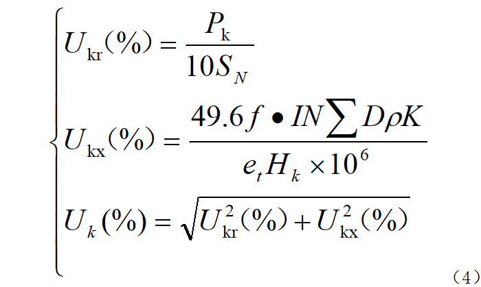
In the formula: Uk, Ukr, and Ukx are the percentage values of the short-circuit impedance, resistance component, and reactance component of the transformer respectively; SN is the rated rating of the transformer. Capacity; f is the frequency; I is the rated current; N is the total number of turns of the transformer; ΣD is the equivalent area of magnetic leakage; ρ is the Roche coefficient; K is the additional reactance coefficient; et is the potential per turn; Hk is the high and low voltage winding the average height.
(5) Temperature rise:
According to the loss value and physical size of the transformer, the temperature rise value of the high and low voltage windings can be determined.
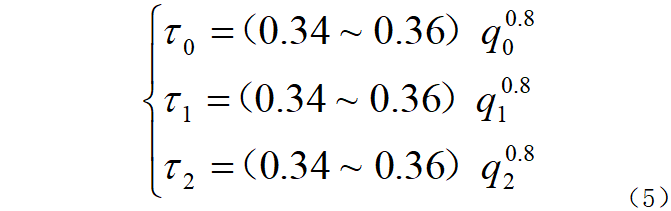
Among them: τ0, τ1, and τ2 are the temperature rises of the iron core and the inner and outer windings respectively; q0, q1, and q2 are the unit heat loads of the iron core and the inner and outer windings respectively.
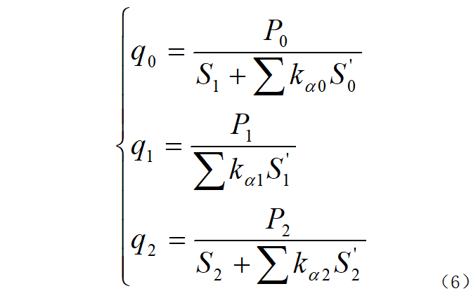
In: P0, P1, and P2 are the losses of the iron core and the inner and outer windings respectively; S1 and S2 are the heat dissipation surface areas of the inner and outer windings respectively; S0', S1', and S2' are the shielded heat dissipation surface areas of the iron core and the inner and outer windings respectively; kα0, kα1, and kα2 are the heat dissipation coefficients of the shielded heat dissipation surfaces of the iron core and the inner and outer windings respectively.
(6) Transformer cost:
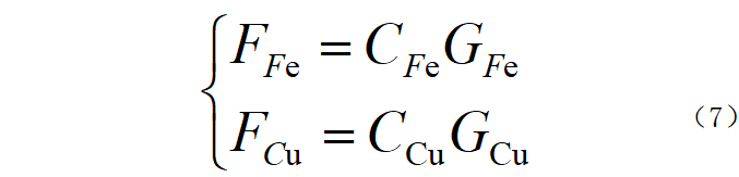
In the formula: FFe and FCu are the core cost and winding material cost (yuan) respectively; CFe and CCu are the unit prices of silicon steel sheets and copper wires (yuan/kg) respectively.
2/Transformer optimization design
The optimization design of traction transformer for coal shearers can be achieved through< u>Intelligentoptimization algorithm implementation. This article uses the particle swarm algorithm to find a solution that optimizes the objective function f(x) and satisfies the constraints in the solution space X.
According to transformer design standards:
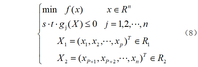
In the formula: f (x) and gj (X) are the objective function and constraint conditions respectively; j is the constraint condition number; X1 and X2 are the iron core and constraint in the optimized solution space respectively. Winding parameters.
Taking the minimum cost of main materials as the optimization goal:

In the formula: f (X1) is the core cost; f (X2) is the winding cost; F (X) is the total cost, and X is a set of data variables. Including x1 and x2 are the length and width of the iron core column respectively, x3 and x4 are the height and width of the window in the iron core respectively, x5~x10 are the conduction width, thickness and length of the high and low voltage windings respectively, x11~x15 are the high and low voltage respectively. Winding spacing, distance from winding to core, distance from transformer to shell, x16 is magnetic density.
The constraint conditions are expressed as g(X)≤0, which mainly include: (1) The magnetic saturation constraint of the transformer core main circuit; (2) The total loss is less than the allowable value; (3) The temperature rise of high and low voltage windings Less than the limit value; (4) The current density of high and low voltage windings is less than the limit value; (5) The short-circuit reactance is not less than the allowable value; (6) The no-load current is less than the national standard; (7) The efficiency is greater than the required value; (8) The spacing between high and low voltage windings , the distance from the winding to the core and the distance from the transformer to the shell meet the insulation requirements. The mathematical expression is shown in equation (10).
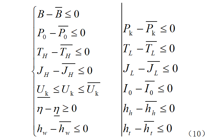
Among them: B, P0, Pk, TH, TL, JH, JL, Uk, I0, η, hh, hw, ht are the core magnetic density, no-load loss, load loss, average temperature rise of high-voltage winding, and average temperature of low-voltage winding respectively. Temperature rise, high-voltage winding conductor current density, low-voltage winding conductor current density, impedance voltage drop, no-load current, transformer efficiency, core height, core length, core width; " ̄" is the upper limit of the corresponding value, "_" is lower limit.
3/Transformer optimization design based on improved particle swarm algorithm
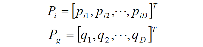
PSO algorithm The flight behavior rules are similar to the movement of birds, and the solution space is iteratively searched by imitating the foraging process of birds [8], which is applied to the optimal design of traction transformers for coal shearers. In order to reduce optimization variables, according to the insulation and heat dissipation design, the high and low voltage winding spacing and winding-to-ground insulation distance adopt the required values under air cooling conditions. For the optimization problem of dimension D, the particle flight in the particle swarm algorithm sets the number of particle swarms to N, and the position of each particle is represented by:

Iterative equation of PSO, the historical optimal position of the particlePi and the population The optimal positionPg is:
Introduce the inertia weight coefficient w to achieve effective control and adjustment of the flight speed of particles. The expressions of the speed and position of particles are:
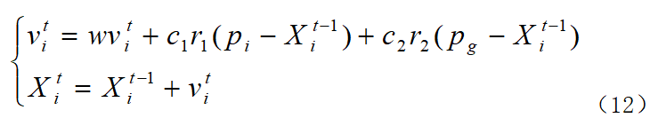
In the formula: T is the total number of iterations; t is The current number of iterations; i represents the particle number, i=1, 2, 3,..., N is the total number of particles; w is the inertia weight; vi is the iteration speed of the i-th particle; Xi is the actual variable corresponding to the i-th particle The value is Yi, and each particle corresponds to a transformer parameter scheme; pi is the historical optimal position of the i-th particle; pg is the historical optimal position of the particle swarm; c1 and c2 are learning factors; r1 and r2 are random numbers in the interval [0, 1].
In order to balance the global search capability and local improvement capability of the PSO algorithm, the adaptive weight coefficient formula is used, and its expression is:

Where: wmax and wmin are the maximum and minimum values of inertia weight respectively; f, favg, fmin are respectively the current objective function value of the particle, the average target value of all particles, and the minimum target value.
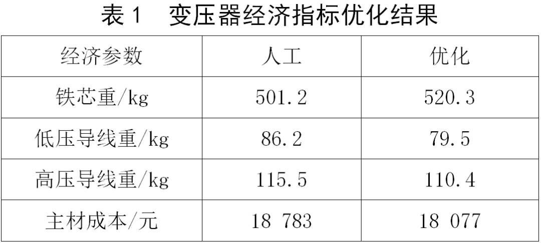
Using the adaptive weight PSO algorithm, the parameters of the 3.3 kV/190 kVA coal shearer traction transformer are optimized through the optimization program. The optimization results of the transformer economic indicators are shown in Table 1, in which the unit prices of the main materials are respectively It is: 8.1 yuan/kg for iron core and 73 yuan/kg for high-voltage and low-voltage winding wires.
for The algorithm efficiency and global convergence are presented, and the evolutionary process is drawn as shown in Figure 2 (for the convenience of observation, the target value every 5 generations is drawn).
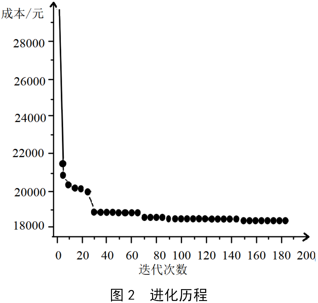
From It can be seen from the figure that the adaptive particle swarm algorithm is used for optimization. When the particle swarm iterates to 185 generations, the group produces the optimal solution. The total consumables cost of the mining traction transformer is reduced by 3.75% compared with the manual traditional design, reaching The purpose of reducing the cost of transformer consumables.
4/Conclusion
The optimization problem of traction transformer for coal shearer was modeled. Analyze and use particle swarm algorithm to solve, which is highly efficient, reduces the cost of major consumables, and can produce higher economic benefits. This optimized design method can also be applied to other dry-type transformers, and has strong flexibility, versatility and practicability.
