-
Mail us
contact@tiger-transformer.com -
Phone us
(+86)15655168738 -


Mail us
contact@tiger-transformer.comPhone us
(+86)15655168738
Simple working schematic diagram of the most basic flyback transformer switching power supply.
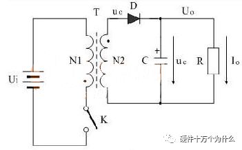
In this circuit system, Ui is the input voltage of the switching power supply, T is the switching transformer, K is the control switch, C is the energy storage filter capacitor, and R is the load resistance. The figure below is the voltage output waveform of the flyback transformer switching power supply. 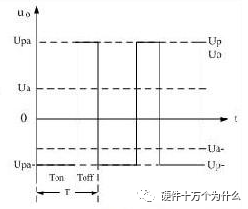
The switching power supply transformer and the switching tube together form a self-excited (or other excited) intermittent oscillator, thereby modulating the input DC voltage into a high-frequency pulse voltage.
In the flyback circuit, when the switch tube is turned on, the transformer converts electrical energy into magnetic field energy and stores it, and releases it when the switch tube is turned off. In the forward circuit, when the switch is turned on, the input voltage is directly supplied to the load and the energy is stored in the energy storage inductor. When the switch tube is cut off, the energy storage inductor will carry out freewheeling flow to the load.
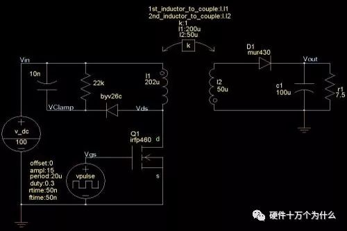
The primary inductance of the transformer is 202uH, but only 200uH is involved in the coupling, so 2uH is the leakage inductance. The secondary is 50uH, no leakage inductance.
The inductance ratio of the transformer is 200:50, which means that the turn ratio of the transformer is NP/NS=2:1. Set the transient scan, the time is 10ms, the step size is 10ns, and the waveform at steady state is: 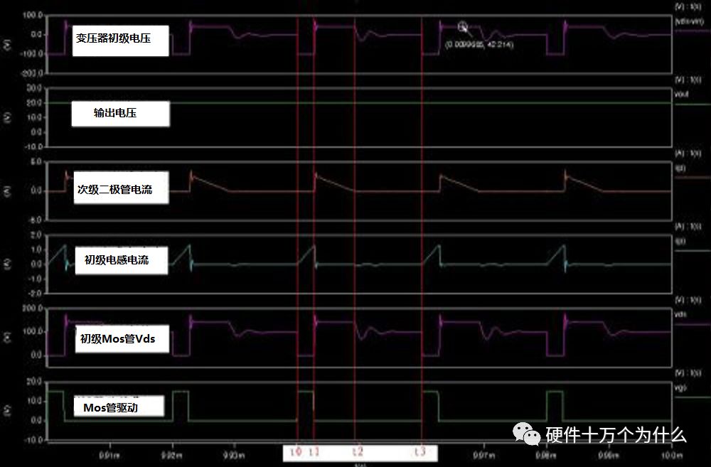
At time t0, the MOS is turned on, and the primary current rises linearly. At time t1, the MOS is turned off, and the primary induced electromotive force is coupled to the secondary to transfer energy to the output capacitor. Leakage inductance produces voltage spikes across the MOS. The output voltage is coupled through the windings and reflected to the primary according to the turns ratio relationship.
These are the same as in CCM mode. This state is maintained until the end of time t2. At time t2, the secondary diode current, that is, the secondary inductor current drops to zero. This means that the energy in the core has been completely released.
Then because the diode current drops to zero, the diode is automatically cut off, the secondary is equivalent to an open circuit state, and the output voltage is no longer reflected back to the primary. Since the Vds voltage of the MOS is higher than the input voltage at this time, under the action of the voltage difference, the junction capacitance of the MOS and the primary inductance resonate. The resonant current discharges the junction capacitance of the MOS.
The Vds voltage starts to drop, and then starts to rise again after 1/4 of a resonance cycle. Due to the existence of the RCD clamp circuit, this oscillation is a damped oscillation with smaller and smaller amplitudes. From t2 to t3, the transformer does not deliver energy to the output capacitor. The output is completely maintained by the output energy storage capacitor.
At time t3, the MOS is turned on again, because the energy of the magnetic core has been completely released before this, and the inductor current is zero. So the primary current rises from zero. 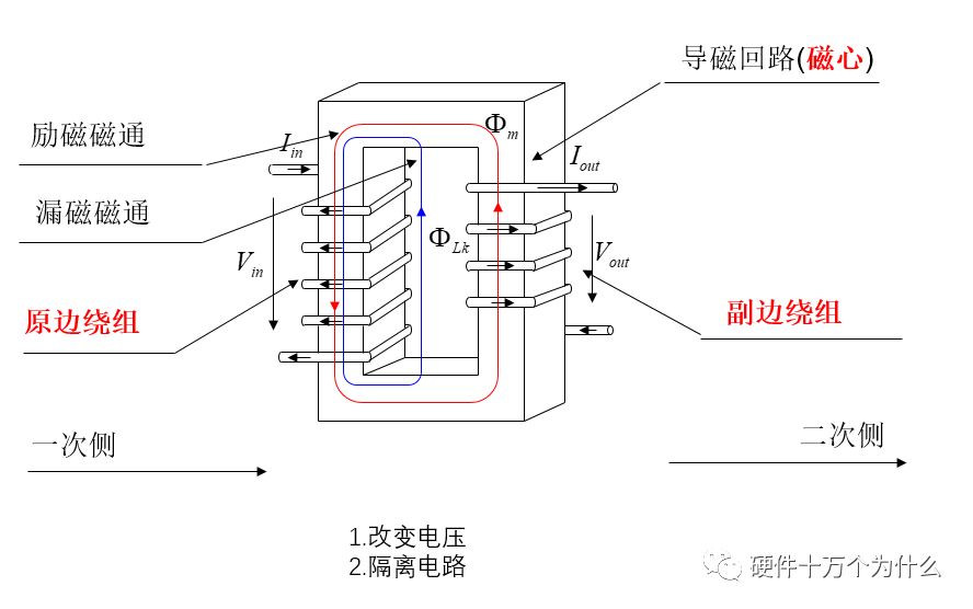
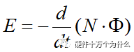
Winding voltage relationship - basic characteristics of transformers Faraday's law: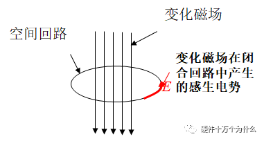
 < br />
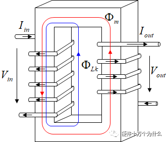
According to Faraday's law, the relationship between input and output voltage is obtained: turns ratio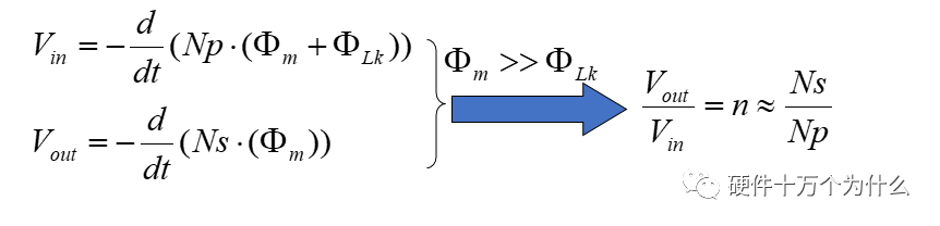
Lenz's law---the current of the transformer is related to the direction of the induced current in the closed loop, always making the magnetic field excited by it "block" the induced current Changes in magnetic flux. 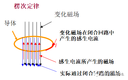

Can be used as a transformer core Soft magnetic material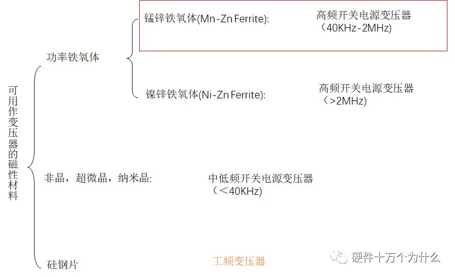
Key points for choosing magnetic materials: A: The saturation magnetic density of the magnetic core B: The loss of the magnetic core (the difference between stored energy and discharged energy)
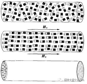
About the saturated magnetic density: Magnetic saturation is a physical characteristic of magnetic materials, which means that due to the limitation of the physical structure of the magnetic permeable material, the magnetic flux passing through it cannot increase infinitely, thus maintaining a certain amount of state.
Magnetic saturation is a physical characteristic of magnetic materials. After magnetic saturation occurs, it is harmful in some occasions, but sometimes beneficial in some occasions. For example, the magnetic saturation voltage stabilizer uses the magnetic saturation characteristics of the core to achieve the purpose of stabilizing the voltage. For power transformers, if the applied voltage greatly exceeds the rated voltage, the current will increase sharply, and the transformer will quickly heat up and burn out.
Assuming that there is an electromagnet, when a unit current is applied, the magnetic induction intensity generated is 1, when the current increases to 2, the magnetic induction intensity will increase to 2.3, and when the current is 5, The magnetic induction intensity is 7, but when the current reaches 6, the magnetic induction intensity is still 7. If the current is further increased, the magnetic induction intensity is 7 and no longer increases. At this time, it is said that the electromagnet has magnetic saturation.
Inductors with magnetic cores have magnetic saturation problems. Adding ferrite or other magnetically permeable cores to inductors can take advantage of their high magnetic permeability to increase inductance and reduce The number of turns reduces volume and improves efficiency. However, due to the limitation of the physical structure of the magnetic permeable material, the magnetic flux passing through it cannot be increased infinitely. The magnetic flux passing through a certain volume of magnetic permeable material will not increase until it reaches a certain amount, no matter how much you increase The current or the number of turns will reach the magnetic saturation. Especially in the loop with DC current, if the DC current has saturated the magnetic core, the AC component in the current will no longer cause the change of the magnetic flux. The inductor will lose its effect.
BH Curve
Use graphics to represent the relationship between the magnetic induction B and the magnetic field H in the process of magnetization of a certain ferromagnetic material A curve, also known as the BH curve. This curve can be measured experimentally. There is a nonlinear relationship between B and H.
When H gradually increases, B also increases, but slowly (oa section). When H continues to increase, B increases sharply and rises almost in a straight line (section ab). When H increases further, B increases slowly again. After reaching point c, even if H value increases again, B hardly changes. If it is increased again, saturation is reached.
Different ferromagnetic materials have different magnetization curves, and their B saturation values are also different. But for the same material, the saturation value of B is certain. 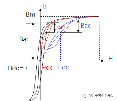
Both magnetic field strength and magnetic induction are physical quantities that characterize the strength and direction of the magnetic field.
Magnetic induction is a basic physical quantity, which is easier to understand. It is the number of magnetic force lines that pass through a unit area perpendicularly. It is directly measured by instruments. Magnetic induction is also called magnetic flux density, or magnetic density for short. It is often expressed by B. Its unit is Weber/square meter (Wb/m^2) or Tesla (T)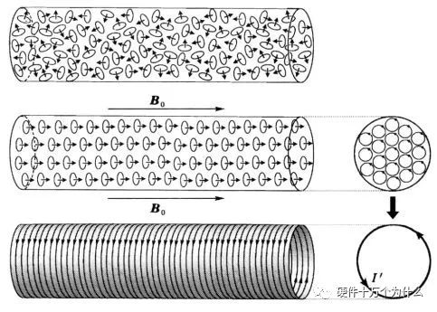
The magnetic field must pass through the medium ( Including vacuum), the medium will also generate a magnetic field due to magnetization, and this part of the magnetic field will be superimposed with the source magnetic field to generate another magnetic field. In other words, after a magnetic field source passes through the medium, the strength and direction of the magnetic field will change
In order to describe the characteristics of the magnetic field source and to facilitate mathematical derivation, a physical quantity H that has nothing to do with the medium is introduced, H=B/u0-M, where u0 is the vacuum magnetic permeability, and M is the magnetization of the medium . This physical quantity is the magnetic field strength. The unit of the magnetic field strength is A/m (A/m).
To put it simply: B is the result (the result of the final magnetic induction), and H is the external cause (the intensity of the single magnetic force applied to the medium by the outside world).
Magnetic loss curve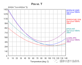
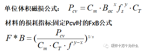
How to select the Bmax of the magnetic core f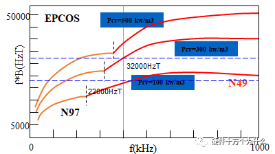
f*B: It shows the ability of B that a material can pass through at a frequency. A. The frequency increases, and the ability of magnetic energy materials to pass power increases. B. The frequency increases to a certain level To a certain extent, there will be a better high-frequency material to replace it. In general, it is necessary to ensure that Bm (maximum magnetic flux density) is less than or much smaller than Bs (saturation magnetic flux density) through design, and the working magnetic flux density is -Bm~Bm any value in between. In special cases, there may be Bm=Bs In general fs 150KHz, Bmax depends on Bs,
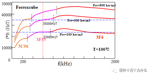
Assume fs=100KHz, take 80% of Bs as the benchmark, the material 3C96, Bmax=0.5*80%*Bs=136mT fs>300KHz, Bmax depends on magnetic loss Pcv Assume frequency fs=400KHz, take unit magnetic loss as 300mw/cc, material N49,
Bmax=32000HzT/400KHz=80mT When fs is between 150K and 300K, both Bs and Pcv are considered, and the smaller value is taken.
Suppose frequency fs= 200KHz, material 3C96, Pcv<300mw/cc B1=0.5*80%*Bs=136mT; B2=28000HzT/200KHz=140mT, take the smaller value of B1 and B2 as Bmax=136mT
< strong>Choose the shape of the magnetic core
| Shape classification | Features | Application |
| EE, ER, EC, ETD | Conventional iron core, low price, large window area, large It is easy to make safety regulations when the power is high. | Low power auxiliary power supply, high power power supply, used in occasions with low power density |
| EFD | Planarized EE core | The application situation is the same as above, and the power density is low, and Low Profile, surface mount or subsidence structure is required |
| PQ,RM | The window area is smaller than that of EE, and Ae is larger than that of EE, | Applied to high power density conditions. Also suitable for output inductors or PFC inductors with small window openings, not suitable for many output transformers |
< tbody>
| Shape Classification | Features | Application |
| PJ | Improved version of POT Core, Ae has large window, small window, good magnetic shielding effect; short height | Used for transformer design with high power density and certain height requirements ;Not suitable for flying wires, not suitable for safety regulation with Margin tape |
| EQ | PJ, the improved version of PQ, the window condition is better than PJ, the height and Ae are better than PQ; the magnetic shielding effect is not as good as PJ | |
| Planar EE | Low height, large Ae, small window; large aspect ratio of center column, not suitable for winding | Transformers and inductors applied to prefabricated windings such as PCB windings |
Wire frame Bobbin:
As the name suggests, the Bobbin (wire frame or skeleton) plays a role in supporting the Coil (coil) in the transformer.
Bobbin's classification:
1. According to the different requirements of the nature of the transformer, it can be divided into thermoplastic materials and thermosetting materials according to the material. The thermoplastic materials we commonly use are nylon (NYLON), plastic (PET), and plastic (PBT). The thermosetting material we commonly use is Bakelite (PM).
2. According to the shape of the transformer, Bobbin is divided into vertical type, horizontal type, mother-in-law type, drawer type, single cell, and double cell.
Features and uses:
1. Bakelite (PM): Thermosetting material, high stability, not easy to deform, temperature resistance 150°C, can withstand 370°C high temperature. The surface is smooth, fragile and cannot be recycled. For transformers with higher temperature resistance.
2. Nylon (NYLON): thermoplastic material, engineering plastic, good ductility, not fragile, temperature resistance 115°C, easy to absorb water, bake at 80°C before use, make Solid and stable. The surface is smooth, translucent and not brittle. Generally used in transformers with strong oil resistance.
3. Plastic (PET): thermoplastic material, 510 system, high hardness, easy to form. Not easy to deform, temperature resistance 170°C, non-smooth surface, not fragile, generally used for bobbin.
4. Plastic (PBT): thermoplastic material, soft, not easy to deform, not resistant to high temperature (160°C), not smooth on the surface, not brittle, generally used for winding tubes