-
Mail us
contact@tiger-transformer.com -
Phone us
(+86)15655168738 -

Mail us
contact@tiger-transformer.comPhone us
(+86)15655168738
For a long time, transformers have been a pain point and difficulty for DC/DC converter designers. Because they are bulky, expensive and difficult to manufacture. By reading this article, you can understand how planar transformers can improve the quality and reduce the design cost of low power DC/DC converters.
What is the difference between a planar transformer and a toroidal transformer?
The transformer is the main heart of any DC/DC converter design and is the key component that determines the overall performance.
Traditional transformers and inductors are wound components. Most mass-produced low-power DC/DC converters use hand-wound toroidal transformers; for transformers requiring up to 6 individual windings with core diameters as small as 6 mm and apertures of 3 mm, development of automated manufacturing processes extremely difficult. Manufacturers such as RECOM have developed automatic winding machines to manufacture such miniature toroidal transformers, but this solution is very difficult.
Planar magnets have been around since the 80s, but the early manufacturing process was expensive, so planar transformers have limited market penetration outside of professional applications. However, with the advancement of manufacturing technology, the cost of planar transformers has been reduced, so new application markets can be developed.
Planar Transformer Design and Construction
Planar transformers or inductors use the copper layers of a multilayer printed circuit board (PCB) to form the windings; The core surrounds the winding, as shown in Figure 1. To form the required number of turns, use hidden vias to connect the PCB layers. Connecting multiple vias in parallel can carry enough current to make a tiny power transformer.
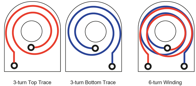
Figure 2: 6-Turn Winding with Two Stacked Layers and a Hidden Via
Figure 2 shows how to form a 6-turn winding by connecting hidden vias through stacked layers. Observe how this arrangement places the ends of the winding outside the ferrite core. Primary and secondary windings are usually interleaved to reduce leakage inductance. Printed circuit boards provide mechanically stable and consistent winding structures suitable for automated production. In addition, the evolution of multilayer PCB structures has allowed epoxy insulation between windings to withstand high isolation voltages between primary and secondary circuits.
Graphic design does present some challenges for the design and manufacturing teams. Because of the difficulty of routing multiple traces on a multilayer PCB, planar transformers are best suited for DC/DC converter topologies that do not require the use of complex transformers, and half-bridge topologies are a common choice.
Even so, there are practical and cost constraints on the number of layers, so planar magnets use high-frequency PWM modulators and drive circuits to reduce the number of turns and layers required. The skin effect caused by these higher frequencies is the main problem they cause. As frequency increases, charge carriers move more and more to the conductor surface, reducing the effective cross-section and increasing I2R losses. Designing the conductor to be flat (rectangular) prevents this skin effect.
Multilayer structure has high coupling capacitance which affects high frequency PWM control. Coupling between planar transformers and conventional circuits must be carefully managed to avoid termination losses. Core air gaps and layered winding proximity cause significant eddy current losses, and due to the different turns ratios, separate PCBs must be designed and tested for each input/output combination.
Once these issues are resolved, planar technology can build extremely low-profile transformers to transmit high power, which in turn allows DC/DC converters to become thinner: the package height of the 15W converter in Figure 1 is only 9.9 mm (0.4 inches)!
Other advantages of planar design are better winding heat dissipation, high density design, low leakage inductance and high power density.
Planar transformers move towards lower power
The previously described benefits make planar transformers an integral part of high power DC/DC converter technology , and RECOM is now integrating planar technology into lower power, smaller converters.
This product uses a multi-layer PCB with through, buried and blind vias to create an industry-leading 12W part in a very compact SIP package with increased power density compared to SIP8 competition 150%.
This voltage regulation design integrates integrated circuits on both the primary and secondary sides of the transformer. The primary-side IC is a wide input, push-pull transformer driver. A synchronous buck stage at the output (secondary side) is used to precisely regulate the load.
Even 1W and 2W DC/DC converters are in the pipeline, starting with two product families. RKK series DC/DC converters have extremely high isolation of 4kVDC/1s and are suitable for industrial markets. Wide operating temperature range of -40°C to +105°C is included as standard without derating. The converter is IEC/EN/UL62368-1 certified for IGBT driver applications.
RYK series DC/DC converter is a low-cost, general-purpose isolated converter with a built-in linear regulator that provides a stable output independent of load.
Moving to a planar transformer allows for a more automated manufacturing process and reduces manual assembly steps, improving design quality. It is also easier to develop custom designs as there is no need to change the transformer windings to accommodate different voltages. The result is shorter turnaround times for custom designs because less testing is required.
The era of planar transformers has arrived, and RECOM uses planar transformers in the DC/DC converter product line to make the most effective use.
