-
Mail us
contact@tiger-transformer.com -
Phone us
(+86)15655168738 -

Mail us
contact@tiger-transformer.comPhone us
(+86)15655168738
Modern power conversion equipment typically uses switching technology, which requires special handling for measurements, including the use of differential probes. This is because, unlike previous analog devices, these devices do not use a transformer to step down the line voltage, but instead use the rectified line voltage as the DC bus power source (Figure 1). This topology has interesting connections to ground and differential signaling.
Modern power conversion equipment typically uses switching technology, which requires special handling when making measurements, including the use of differential probes. This is because, unlike previous analog devices, these devices do not use a transformer to step down the line voltage, but instead use the rectified line voltage as the DC bus power source (Figure 1). This topology has interesting connections to ground and differential signaling.
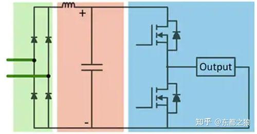
Figure 1: Switch mode power converter shown Functional block diagram of a power converter for full-wave rectification of line voltage to generate dc bus voltage. (Image source: Teledyne LeCroy)
In the configuration of Figure 1, the circuit performs full-wave rectification of the AC line. For a 120 Vrms AC line, the peak-to-peak voltage is 340 VAC. The full wave rectified voltage of the capacitor is 170 VDC. For 240 V lines these values will be doubled. This can be used as a DC power supply for a switch mode regulator.
The power switches are configured as a half-bridge topology, with upper and lower switches alternately connected to the output. A voltage regulator (not shown) generates a pulse-width modulated (PWM) signal that regulates the output voltage by driving the MOSFET's gate-to-source voltage.
Why do you need a differential probe
In Figure 1, there are a few points to note. First, no point in the circuit is referenced to ground. The input line has live wire and neutral wire. The neutral wire is referenced to ground at its source and may be a few volts off ground before reaching the powered device. The voltage of the power converter is basically a floating voltage. When trying to measure voltage with an oscilloscope using a common passive probe, you need to connect the oscilloscope ground lead somewhere. Connecting a ground wire to any point of this circuit can cause problems.
The second thing to note is that the upper MOSFET voltage sits on the lower MOSFET's drain voltage. This voltage switches between zero volts and the DC bus voltage. This presents another problem for oscilloscope measurements that are grounded.
The solution to this measurement problem is to use a differential probe.
Given the encountered voltages of up to 680 V, a high-voltage differential probe is necessary (Figure 2).

Figure 2: Shown is a functional block diagram of a high voltage differential probe , the probe does not need to be grounded because it measures the voltage difference between the + and – probe inputs. (Image source: Art Pini)
Differential probes measure the voltage difference between input terminals. High voltage differential probes include attenuators and provide overload protection on each input. Typical attenuation values are in the range of 50:1 to 2000:1. Therefore, the input voltage range of the high voltage differential probe is 1500 to 7000 V.
The device under test is modeled as a differential source consisting of two differential sources, a positive component (VP) and a negative component (VN) and a common-mode component (VCOM). The common-mode component is shared with the + and – inputs. The + input corresponds to VP + VCOM, the – input corresponds to VCOM - VN. Ideally, the probe would measure the difference between these input voltages, or VP +VN, thereby canceling out the VCOM term. A real differential probe will attenuate the common-mode voltage, but not completely eliminate it. The common-mode rejection ratio (CMMR) of a differential probe, the ratio of the attenuated common-mode signal to its unattenuated amplitude, is expressed in dB and indicates the effectiveness of the differential probe. This figure of merit is frequency dependent and generally decreases with increasing frequency.
How to use a differential probe
Let's see how to use a high voltage differential probe to measure the upper gate source of a 120 V input switch mode power converter (similar to the one in Figure 1) Voltage. The DC bus voltage is approximately 170 V. The gate-source voltage of the upper MOSFET will depend on the switching signal of the lower MOSFET, which is a PWM signal switching between 0 and 170 V. This gate-source voltage will be on the order of 4 to 12 V.
Teledyne LeCroy's HVD3106A-NOACC High Voltage Differential Probe is recommended for this measurement. This 120 MHz bandwidth probe is rated at 1000 V RMS. With a differential rating of 1500 V (DC plus AC peak), it is even perfectly matched to 240 V AC power converters. The probe has a 1500 V offset range, making it easy to vertically expand the measured waveform to see details. The probe's CMRR is 85 dB up to 60 Hz and 65 dB at 1 MHz. This means that the attenuation of the 170 V common mode signal will be better than 65 dB. The amplitude of the attenuated common-mode signal is about 95 mV. Since the gate-source voltage is on the order of 4 to 12 V, common-mode interference has little effect on the measurement.
For higher voltages, such as those associated with 1500 VDC solar photovoltaic (PV) inverter measurements, the HVD3206A probe is recommended. This probe has a maximum differential voltage rating of 2000 V (dc plus peak ac) and has the same bandwidth and CMRR as the HVD3106A-NOACC probe.
Finally, for large three-phase machines and their controllers, it is recommended to use the HVD3605A high-voltage differential probe, whose maximum voltage input is 7000 V (DC plus AC peak value). Such a high voltage range is possible due to the presence of 200:1 or 2000:1 attenuators in the probe. The probe's CMRR is 85 dB at 60 Hz, 70 dB at 10 kHz, and 64 dB at 1 MHz with an offset range of 6000 V.
The HVD3000A series probes all have a gain accuracy of 1% or better, are available with and without accessories, and the oscilloscope cable lead lengths are 2.25 m and 6 m respectively.
Accessory kits vary by model and include clips or small grippers for different voltages.
Conclusion
High-voltage differential probes are useful in situations where there is no ground reference and the signal under test depends on another high-voltage signal. For these situations, Teledyne LeCroy has introduced the HVD3000A series probes. All of these probes are ideal for measurements on switch-mode power converters that require ground isolation. They are fully integrated into the Teledyne LeCroy oscilloscope operating system and automatically sense and scale for accurate measurements.
