-
Mail us
contact@tiger-transformer.com -
Phone us
(+86)15655168738 -


Mail us
contact@tiger-transformer.comPhone us
(+86)15655168738
The various electrical appliances we encounter in our daily lives, such as the most common digital cameras, mobile phones, video cameras, printers, etc., all use controllable rectified power circuits, so this Circuits are very popular and are the first thing everyone should master when learning circuits.
The following shows one of the most commonly used classic rectifier circuits in work and analyzes its working details.
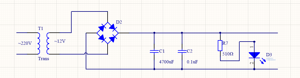
The controllable rectified power supply circuit in the above figure can be based on It is required to provide the stable voltage and current required by subsequent electrical appliances. According to the parameters of the rectified power supply circuit in the picture, it can be seen that it can output a 12V, 500mA DC power.
This picture combines a transformer, a bridge rectifier circuit and a capacitor filter circuit to form a classic stable rectifier circuit. Next, Brother Wang will analyze the working principle of this circuit diagram with everyone.
First of all, the AC 220V mains power at our home is connected to the left side of the picture above. After passing through the transformer T1, the AC 22V mains power will be adjusted to AC 12V by the transformer, and then it will enter the bridge rectifier circuit. D2 link, this part of the circuit can convert 12V AC power into 12V DC power and then send it out. Next, the DC power passes through capacitor C1 and capacitor C2. The function of capacitor C1 here is to filter the AC power in the rectified DC power again to obtain a better Pure direct current.
The function of connecting a small capacitor C2 in parallel with the large capacitor C1 is to obtain better direct current. After the above steps, a stable 12V DC power has been obtained.
The light-emitting diode D3 at the back end of the circuit functions as a power indicator light, which can visually show whether the circuit is working normally. Resistor R7 is the current limiting resistor of the light-emitting diode.
The maximum output current of the rectified power supply circuit in the figure above depends on the power of transformer T1 and the specifications of the rectifier diode. Therefore, if we want to output a larger current, we should increase the power of transformer T1 and the maximum rectified current value that the rectifier diode can carry. If we want to change the output voltage, then changing the secondary voltage of transformer T1 will do.
Another thing to consider is the value of resistor R7 to ensure that the working circuit of light-emitting diode D3 is around 10mA.
Because the output voltage is changed, this resistance must be changed. It is a current-limiting resistor. When the voltage becomes larger, the light-emitting diode basically has a fixed voltage drop of 2V, then the voltage withheld by resistor R7 will increase. If the resistance value is not adjusted in time, the current flowing through resistor R7 will increase and burn out the light-emitting diode.