-
Mail us
contact@tiger-transformer.com -
Phone us
(+86)15655168738 -


Mail us
contact@tiger-transformer.comPhone us
(+86)15655168738
1. First, let’s talk about what coupling is? Coupling, in layman's terms, is a connection. In ancient times, coupling refers to farm tools, and by extension, it refers to two people working side by side in the farmland. In terms of amplifier circuits, it refers to two circuits. The first circuit can affect the second circuit (such as a first-level amplifier circuit and a second-level amplifier circuit). Then a component is used to connect the two circuits. For example, using a capacitor or transformer to connect, this connection is called coupling. Because of the different connection methods, coupling can be divided into resistor-capacitor coupling, direct coupling, transformer coupling, etc. The figure below shows a two-stage amplifier circuit resistor-capacitor coupling, or AC coupling, which means that resistor-capacitor coupling can only be used for Amplify AC signals.
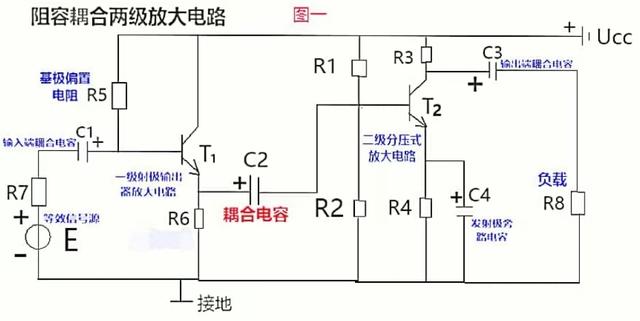
Second, several explanations on coupling: The first picture above is Two-stage amplifier circuit, the front-stage amplifier circuit is connected to the next-stage amplifier circuit through the coupling capacitor C2. C2 plays the role of connecting the two amplifier circuits, so the capacitor C2 is also called the coupling capacitor. This capacitor is used to amplify the front-stage amplifier circuit. The way the circuit is connected to the post-amplification circuit is also called resistance-capacitance coupling.
The purpose of the coupling capacitor C2 is to block DC, so that the DC working states of the front and rear amplifier circuits do not affect each other, and their respective static working points (because the static working point is an indicator of the DC state, The capacitor C2 blocks DC, so the static operating point is independent, so that the voltage of the output signal of the previous stage is transmitted to the input end of the latter stage almost losslessly.
Disadvantages of coupling capacitors: Resistor-capacitor coupling is generally used to amplify AC signals, while slowly changing voltage signals such as those caused by temperature sensors are generally connected by direct coupling, that is, the output terminal of the first stage is directly connected. Connect to the input of the second stage.
3. How to find the DC path and AC signal transmission route in the two-stage amplifier circuit? See Figure 2 below for details.
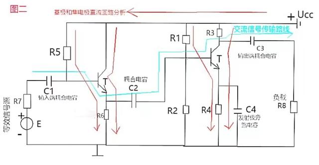
There are two DC paths : The first path is the DC power supply Ucc added to the triode collector-emitter-ground. The second path is the DC power supply Ucc added to the base of the transistor - the emitter - to ground. In other words, both transistors have DC feedback.
AC signal transmission route description: For the AC component, the input coupling capacitor C1, the coupling capacitor C2, and the output coupling capacitor C3 can be regarded as short circuits, while the DC power supply Ucc The internal resistance is generally very small (such as AA dry batteries) and can be ignored. For AC, this DC power supply can be regarded as a short circuit. The resistor R7 and electromotive force E are equivalent to the AC signal source.
Instructions for the two triode emitters: The triode emitter of the first-stage amplifier circuit (the amplifier circuit on the left) has no bypass capacitor (C2 is the first- and second-stage amplifier The coupling capacitance of the circuit), then the emitter resistor R6 of the first triode is the feedback resistor; the emitter of the second triode has a bypass capacitor C4, then the AC component of the R4 resistor is bypassed by C4, so the second triode The emitter only has DC feedback and no AC feedback.
Let’s analyze the AC signal transmission route: The AC signal source of the first-stage amplifier circuit (that is, the resistor R7 and the electromotive force E are equivalent to the AC signal source) sends out a signal --- -Input coupling capacitor C1----transistor emitter (this connection method of the emitter output is generally called an emitter output, that is, it is output from the emitter. The collector power supply Ucc can be regarded as a short circuit for AC signals. So the collector is the common terminal between input and output)----coupling capacitor C2---second-stage amplifier circuit transistor collector----output coupling capacitor C3----load (resistance R8 is equivalent to the load resistance ).
The capacitor C4 is the emitter AC bypass capacitor, which can bypass the AC component on the resistor R4, so there is no AC feedback on R4, only DC feedback.