-
Mail us
contact@tiger-transformer.com -
Phone us
(+86)15655168738 -

Mail us
contact@tiger-transformer.comPhone us
(+86)15655168738
In the process of power supply design and debugging, when we encounter problems, we should put our thoughts into the inside of the power supply, and if we are in the power control part, what should we do if we encounter such problems? solve. That is to consider the problem from the perspective of the other party. This time we will take the common flyback as an example, using the most commonly used 384x series ic as the blueprint, to see how an ordinary flyback circuit starts to send out pulses to transfer energy and finally achieves a stable voltage, and how it is restored after encountering a disturbance. How to adjust automatically.
1. How does the power start
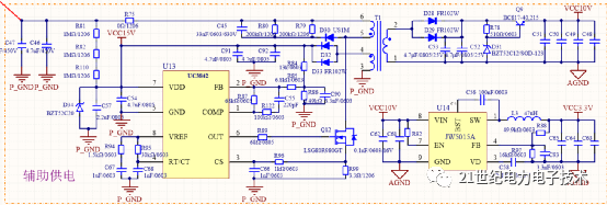
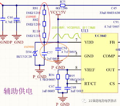
For a flyback power supply made of 384X, it is generally unrealistic to use an additional VCC power supply. The startup of the power supply is realized through the startup capacitor and the startup resistor. From VCC Connecting a resistor to the rectified input bus, I call it a starting resistor, and connecting a capacitor from VCC is called a starting capacitor.
Generally speaking, the current flowing through the start-up resistor should be guaranteed to be above 0.5mA when the input voltage is the lowest (of course, the larger the current, the faster the power supply starts , but the loss of the corresponding resistance is greater).
When starting, the IC should pay attention to two voltage points, one is called the starting voltage, and the other is called the cut-off voltage. For 42 and 44, the starting voltage is 16V, and the cut-off voltage is 10V. It did not consume power before, so the current flowing through the starting resistor will charge the starting capacitor, and the voltage of the starting capacitor will gradually increase. When the capacitor voltage reaches the IC startup voltage, the IC starts to output pulses. The circuit started working.
When the IC starts to work, the current flowing through the starting resistor cannot meet the working needs of the IC. The excess energy is provided by the starting capacitor, and the capacitor voltage begins to gradually decrease. When the capacitor voltage drops to the IC When the cut-off voltage is reached, the IC stops working, so before the voltage on the capacitor drops to the cut-off voltage of the IC, there must be another circuit to provide the current required for the IC to work, otherwise there will be a phenomenon of startup failure. When the IC fails to start, the IC does not consume current, and the capacitor voltage gradually increases. Repeating this, this is what many engineers have mentioned many times, why the VCC voltage is a triangle wave.
2. VCC abnormality can be caused by the following points Check
(1) Whether the auxiliary power supply winding is added
(2) Whether the end of the VCC winding with the same name is correct
(3) Whether the number of winding turns is enough
p>
(4) Look at the resistor connected in series with the auxiliary winding, is it a bit too large? Try a short circuit first before talking
3. What is a hiccup?
A hiccup is a constant When you supply power to your PWMchip by charging and discharging the capacitor through the startup circuit, the voltage of the auxiliary winding will not rise all the time.
4. How to work after startup
When the voltage on the startup capacitor reaches the working voltage of the IC, the IC starts to work and sends out the first driving pulse.
What is the duty cycle of the first driving pulse? I believe many netizens have asked about it. The duty cycle should be the maximum duty cycle, after all, the loop is open at this time. But if there are other restrictions inside the IC, then I don’t know. However, how meaningful is the first duty cycle to us? I don’t want to develop and make ICs.
When the drive pulse is sent out, the MOS tube is turned on, the voltage across the transformer becomes the bus voltage, the transformer is regarded as an inductance, the inductance is the primary inductance value of the transformer, the voltage across the inductor is VIN, and the duration is DT, then the inductor current is VDT/L before the MOS tube is turned off, and the energy stored in the inductor will not be mentioned, so I will not ask.
When the MOS tube is closed, find a way to release the energy stored in the inductor, otherwise it can only self-explode (break down the air arc). There are two loops, one is to break down the MOS tube, through Input discharge, one is to charge the output capacitor after being rectified by the output diode, if your circuit chooses the first path, congratulations, the circuit parameter selection is wrong. However, when the first pulse appears, this phenomenon does not seem to happen, because the output of the secondary side has no voltage yet, and the secondary side is equivalent to a short circuit. Therefore, the energy can only charge the output capacitor after passing through the rectifier diode to increase the output voltage.
If the filter capacitor is selected very small, that is, 0.5LII is greater than 0.5CUU, then the energy stored in the inductor in the first cycle is enough to raise the output filter capacitor voltage Above the designed output voltage, the circuit is closed. . . . Of course, generally speaking, the output filter capacitor of the flyback is selected to be relatively large, and the energy stored in the transformer in the first turn-on cycle should not be enough to fill the output capacitor. (Not calculated here, estimated).
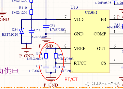
5. The role of RT/CT
The RT and CT we set are actually setting the charging and discharging time, that is, the frequency. The capacitor is charged through RT, and the charging time is the conduction Time, after the CT voltage reaches a set value, the comparator (whatever it is, that’s what it means) flips over, and a constant current source discharges the CT, and the CT discharge time is a dead zone.
6. Load regulation, power supply action
When the load is suddenly increased, the circuit does not respond, that is, the energy transmitted to the secondary side does not change at the moment of increasing the load, but the energy consumed by the load increases, what will happen? Only when the output voltage drops and the circuit detects that the output voltage drops, will there be an action.
7. What’s wrong with the power supply, the load capacity is a bit weak
As mentioned earlier, if the first pulse cycle, the energy delivered by the transformer to the secondary side is enough to make the output voltage When the set value is reached, the loop is closed. Then the voltage converted to the auxiliary auxiliary winding is also enough to maintain the work of the IC, so there is no need to worry about whether the energy stored in the starting capacitor is enough to start the power supply. But under normal circumstances, the energy stored in a cycle transformer is not enough to increase the output voltage to the set value, so multiple cycles of energy transfer are required. Each cycle the output voltage increases a little until it reaches the set value. But it should be noted that the bootstrap capacitor must be strong before the output voltage reaches the set voltage. If it cannot support it, it will fail to start again, and the situation mentioned above will occur.
From the above description, we can see that if the output capacitor is relatively large, or the output is overloaded, the power supply will be more difficult to start. I believe that many experienced engineers have encountered it. Why do I The power supply, the no-load output voltage is stable and the load output just jumps? When encountering this kind of phenomenon, I usually suggest to increase the output capacitor first, if it still doesn’t work, then look for other problems.
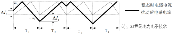
8. What is sub-harmonic oscillation?
In the design of practical switching power supply, the sub-harmonic oscillation is described as follows: In the current control mode When the current reaches a certain level (determined by the output of the error amplifier), the switch is turned off. If the duty cycle exceeds 50%, the rise time of the inductor current is greater than 50% of the entire cycle, and the current The drop time is less than 50% of a cycle. In a short period of time, the inductor current has not had time to return to the static initial value, and the next cycle begins, and the initial current of the next cycle becomes larger. In the next cycle , the inductor current quickly rises to the reference point, shortening the on-time and narrowing the duty cycle. The duty cycle of this cycle is reduced to less than 50%, but this leads to a too long off-time, and the next The initial value of the current for the cycle is too small, causing the duty cycle of the next cycle to exceed 50% again. Over and over again, there will be a shock with a period of too large and too small, which is called a sub-slope shock.
The second slope oscillation only appears in the current mode control, increasing the slope compensation is to change the current mode control to the voltage mode control.