-
Mail us
contact@tiger-transformer.com -
Phone us
(+86)15655168738 -


Mail us
contact@tiger-transformer.comPhone us
(+86)15655168738
Overvoltage protection. The power supply provides stable power to external devices. Each device will have a maximum allowable voltage during normal operation. When the voltage provided is too high, the device will be damaged within a certain period of time, so power supply overvoltage protection is very necessary.
There are many ways to test overvoltage. The most commonly used method is to short-circuit pins 1 and 2 of the optocoupler, and use an oscilloscope to see the maximum value the output voltage reaches. If there is no optocoupler (primary feedback PSR structure), short the bias resistor at the foot of FB.
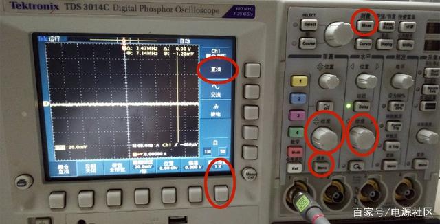
1. Set up the oscilloscope, select Menu->DC, select Menu->Probe Setting 1 (the same as the probe selection multiple). Select Measure->Maximum. Twist the scale -> set to 2V per division (this depends on the power supply output voltage). Twist the scale -> set to 1S per division. Set as shown below.

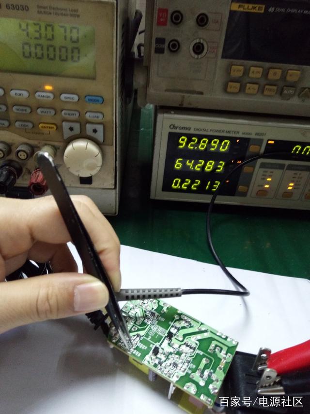
Connect the power supply to the output end. After turning on the power without load, use tweezers to short-circuit pins 1 and 2 of the optocoupler. Please be careful not to touch the primary end of the transformer during the test. The primary end voltage is higher and more dangerous.
Observe the oscilloscope and you will see The output voltage will first rise and then fall. The overvoltage point of the following power supply is 7.32V.
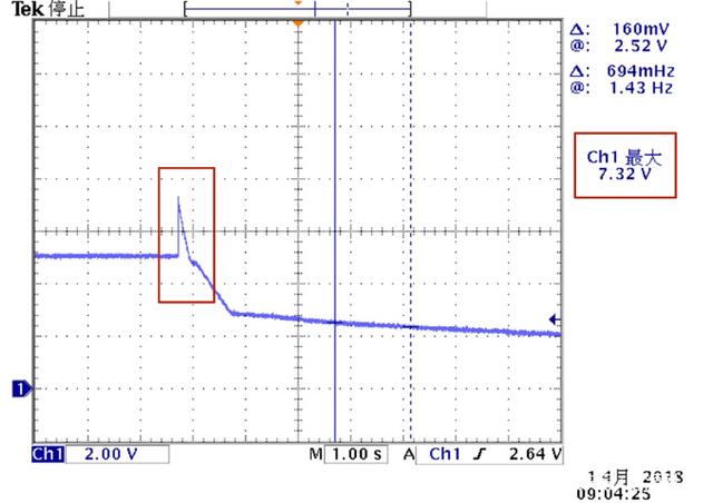
Tested more Test several times and take the maximum value. At the same time, each input AC voltage and each load should also be tested and the data should be recorded. Generally speaking, the overvoltage point is the largest when no load is applied.