-
Mail us
contact@tiger-transformer.com -
Phone us
(+86)15655168738
Mail us
contact@tiger-transformer.comPhone us
(+86)156551687381 Rectified power supply
The principle of rectified power supply is to use the unidirectionality of diodes to convert AC into DC.
Commonly used rectified power supplies include single-phase half-wave rectifier circuits, single-phase bridge rectifier circuits, three-phase rectifier circuits and their waveforms.
1.1 Single-phase half-wave rectifier circuit
Single-phase half-wave rectifier circuit is the simplest kind of rectifier circuit.
The principle model is as follows:
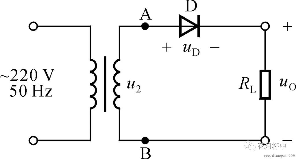
The principle is as follows:
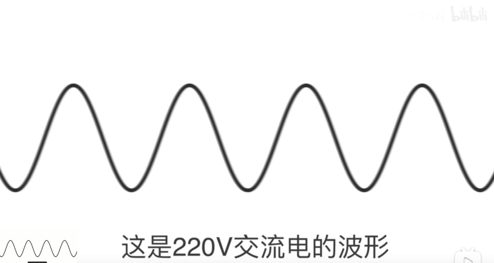
During the positive half cycle, a forward voltage is applied to the diode, so it is in a conducting state.
During the negative half cycle, a reverse voltage is applied to the diode, so it is in a cut-off state.
1.2 Single-phase full-wave rectifier circuit
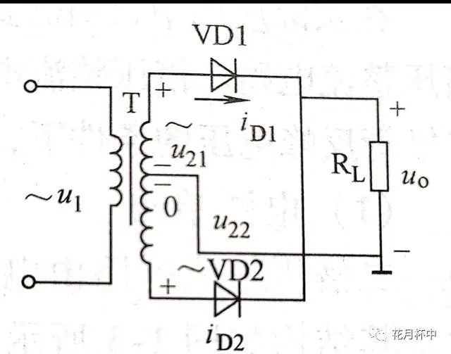
The single-phase full-wave rectifier circuit is composed of two sets of single-phase half-wave rectifier circuits.
The principle model is as follows, the principle is similar to half-wave rectification:
 < /p>
< /p>
1.3 Single-phase bridge rectifier circuit
Bridge rectifier is an improvement on the single-phase full-wave rectifier circuit.
The principle model is as follows:
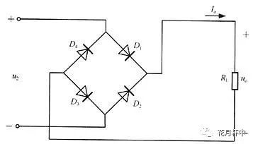
The principle is as follows:
Use four diodes and connect them two by two.
During the positive half cycle, the two tubes D1 and D3 are turned on, and a positive output is obtained;
During the negative half cycle, the two tubes D2 and D4 are turned on, so the output is still a sine wave. positive half of .
The efficiency of the bridge rectifier in utilizing the input sine wave is twice as high as that of the half-wave rectifier.
1.4 Three-phase bridge rectifier circuit
The three-phase bridge rectifier circuit converts three-phase AC power into AC/DC.
Three-phase AC power supply is a power supply composed of three alternating currents with the same frequency, equal amplitude, and phase differences of 120° from each other.
The principle model is as follows:
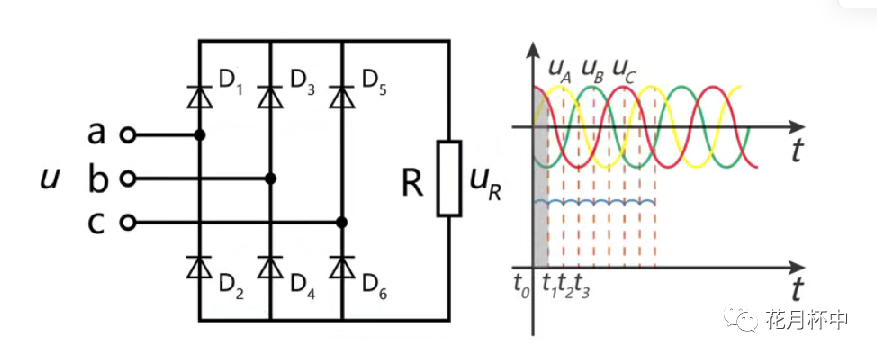
The principle is as follows:
After the three-phase AC power is transformed by a three-phase transformer, it is connected to terminals a, b, and c of the three-phase bridge circuit.
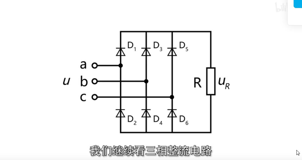
The six diodes in the picture are divided into two groups. The first group D1, D3, and D5 are connected with a common negative (cathode) pole, and the second group D2, D4, and D6 are connected with a common positive (anode) pole.
The three diodes in each group conduct in turn. In a common cathode group, the diode with the highest anode potential is turned on; in a common anode group, the diode with the lowest cathode potential is turned on.
At the same time, only one diode in each group is conducting, and the others are not conducting.
1.5 Three-phase half-wave rectifier circuit
The three-phase half-wave rectifier circuit is a simplified version of the three-phase bridge rectifier circuit.
The principle model is as follows, the principle is similar to the three-phase full-wave rectifier circuit:
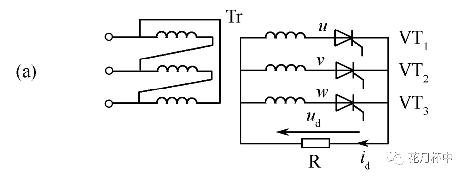
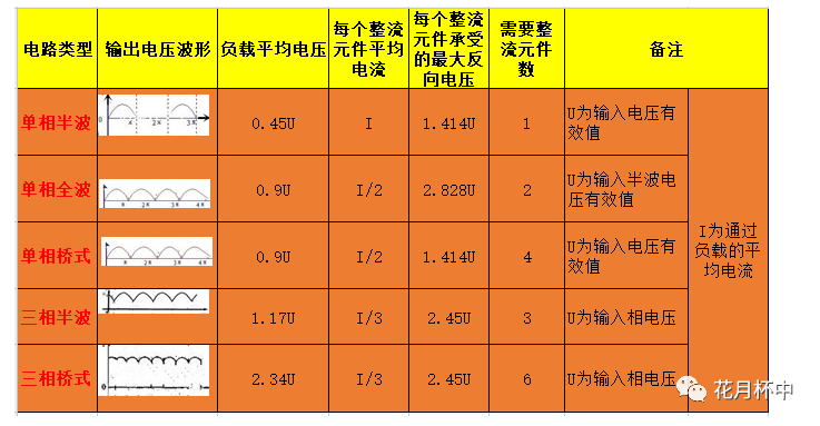
1.6 Comparative analysis of five types of rectifier circuits
1) The half-wave rectifier circuit is the simplest, but has low output voltage, large fluctuations, and low efficiency; it is used in applications that do not require power supply waveforms. High occasions;
2) The output voltage of single-phase full-wave rectification is high, and the current passing through the diode is small, but it requires two triodes, a transformer tap, and the reverse voltage the diode withstands is high, so it is rarely used;
3) The output voltage of single-phase bridge rectifier is high, the current passing through the diode is small, the waveform is good, the efficiency is high, and the diode withstands low reverse voltage; the disadvantage is that it requires 4 diodes; but this circuit has outstanding advantages , it is widely used, especially the emergence of rectifier bridge, which makes the circuit more concise.
4) Three-phase half-wave rectifier circuit, the circuit is simple, the voltage pulsation is better than single-phase, and less transistors are used;
5) Three-phase bridge rectifier circuit, the voltage pulsation is better The lowest, the output voltage is the highest;
