-
Mail us
contact@tiger-transformer.com -
Phone us
(+86)15655168738 -

Mail us
contact@tiger-transformer.comPhone us
(+86)15655168738
Introduction to Stabilizers:
Embedding Microprocessing in the Design of a Smart AC Voltage Stabilizer (or Automatic Voltage Regulator (AVR)) device chip technology and power electronics, resulting in a high-quality, stable power supply in the presence of significant and continuous deviations in mains voltage.
As an advancement of traditional relay-type voltage regulators, modern innovative voltage regulators use high-performance digital control circuits and solid-state control circuits, eliminating the need to adjust potentiometers and allowing users to set voltage requirements through the keyboard and have output Start and stop functions.
This also results in the stabilizer having a very slow trip time or response, typically less than a few milliseconds, additionally this can be adjusted via variable settings. Today, stabilizers serve as an optimized power supply solution for many electronic devices that are sensitive to voltage fluctuations, and they have been found used with many devices such as CNC machines, air conditioners, televisions, medical equipment, computers, telecommunications equipment, etc.
What is a voltage regulator?
It is an electrical appliance designed to supply a constant voltage to a load at its output terminals, regardless of changes in input or input supply voltage. It protects equipment or machines from overvoltage, undervoltage, and other voltage surges.
It is also called an automatic voltage regulator (AVR). Voltage stabilizers are the first choice for expensive and precious electrical equipment to protect them from harmful low/high voltage fluctuations. Some of these equipment are air conditioners, offset printing machines, laboratory equipment, industrial machines and medical equipment.
A voltage regulator regulates fluctuating input voltage before feeding it to a load (or device sensitive to voltage changes). Within a given input voltage fluctuation range, the output voltage of the stabilizer will remain within the range of 220V or 230V in the case of single-phase power supply, and within the range of 380V or 400V in the case of three-phase power supply. This regulation is performed by buck and boost operations performed by internal circuitry.
There are a variety of automatic voltage regulators on the market today. These can be single phase or three phase units depending on the type of application and capacity (KVA) required. There are two versions of the three-phase stabilizer, namely the balanced load model and the unbalanced load model.
These can be used either as dedicated units for appliances or as large stabilizer units for entire appliances in a specific place, such as an entire house. Furthermore, these can be either analog or digital type stabilizer units.
Common voltage stabilizer types include manual or switchable stabilizers, automatic relay-type stabilizers, solid-state or static stabilizers, and servo-controlled stabilizers. In addition to the stabilization function, most stabilizers also have additional functions such as input/output low-voltage cut-off, input/output high-voltage cut-off, overload cut-off, output start and stop functions, manual/automatic start, voltage cut-off display, zero-voltage switch, etc.
Why do you need a voltage regulator?
Generally, every electrical equipment or device is designed for a wide range of input voltages. Depending on the sensitivity, the operating range of the device is limited to a specific value, for example, some devices can withstand ±10% of the rated voltage, while others can withstand ±5% or less.
Voltage fluctuations (increases or decreases in rated voltage magnitude) are common in many areas, especially on terminated wiring. The most common causes of voltage fluctuations are lighting, electrical faults, wiring faults and periodic equipment shutdowns. These fluctuations can cause accidents to electrical equipment or appliances.
Can cause long-term overvoltage
Permanent damage to equipment
Winding insulation damage
Unnecessary interruptions in the load
Increased losses in cables and related equipment
Reduced service life of equipment
Long-term undervoltage can lead to
equipment failure
Longer operating time (e.g. resistance heater)
Equipment performance degrades
Sinking large currents, further causing overheating
Calculation errors
Motor speed decreases
Thus, voltage stability and accuracy determine the correct operation of the equipment. Therefore, a voltage regulator ensures that voltage fluctuations in the input power supply do not affect the load or appliance.
How does a voltage regulator work?
Basic principles of voltage regulators, used to perform buck and boost operations
In voltage regulators, voltage correction under overvoltage and undervoltage conditions is accomplished through two basic Operations are performed, namely boost and buck operations. These operations can be performed manually via switches or automatically via electronic circuits. Boost operation increases the voltage to the rated level during undervoltage conditions, while buck operation reduces the voltage level during overvoltage conditions.
The concept of stabilization involves adding or subtracting the voltage from the mains supply. To perform such tasks, stabilizers use transformers, which are connected to switching relays in different configurations. Some stabilizers use transformers with taps on the windings to provide varying voltage corrections, while servo stabilizers use automatic transformers for a wide range of corrections.
To understand this concept, let us consider a simple step-down transformer of 230/12V rating and its connection to these operations as shown below.
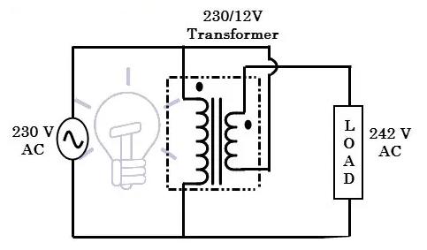
The above figure illustrates the boost configuration with the secondary winding The polarity is oriented so that its voltage adds directly to the primary voltage. Therefore, during undervoltage conditions, the transformer (whether it is a tap changer or an autotransformer) is switched by a relay or solid state switch so that additional volts are appended to the input voltage.
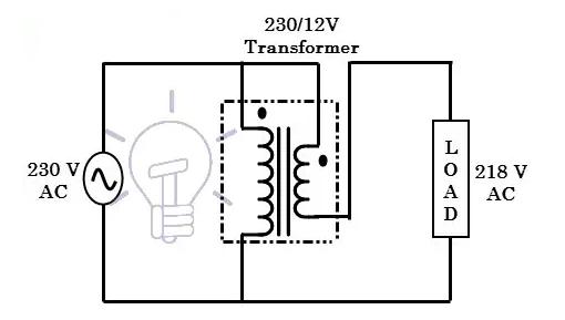
In the above figure, the transformer is connected in a step-down configuration, where The polarity of the secondary coil is oriented so that its voltage is subtracted from the primary voltage. During an overvoltage condition, the switching circuit converts the connection to the load to this configuration

The above figure shows a two-stage voltage regulator that uses two relays to provide constant AC power to the load during overvoltage and undervoltage conditions. By switching the relay, buck and boost operations can be performed for two specific voltage fluctuations (one undervoltage, such as 195V, and one overvoltage, such as 245V).
For a tap transformer type stabilizer, different taps are switched depending on the amount of step-up or step-down voltage required. However, in the case of automotive transformer type stabilizer, a motor (servo motor) is used with sliding contacts to obtain step-up or step-down voltage from the auto-transformer as it contains only one winding.
Types of voltage regulators
Voltage regulators have become an integral part of many household, industrial and commercial system appliances. Previously, manually operated or switchable voltage regulators were used to step up or step down the input voltage to provide an output voltage within the desired range. This stabilizer is made from electromechanical relays as switching devices.
Later, additional electronic circuits automated the stabilization process and gave rise to the tap-changer automatic voltage regulator. Another popular type of voltage stabilizer is the servo stabilizer, where voltage correction occurs continuously without any switching. Let us discuss the three main types of voltage regulators.
Relay Type Voltage Regulator
In this type of voltage regulator, voltage regulation is achieved by switching a relay so that one of the multiple taps of the transformer is connected to load (as mentioned above), whether for boost or buck operation. The figure below shows the internal circuit of a relay type stabilizer.
In addition to the transformer, it has electronic circuits and relay banks (which can be toroidal or core transformers with taps on the secondary). Electronic circuits include rectifier circuits, operational amplifiers, microcontroller units, and other tiny components.
The electronic circuit compares the output voltage to a reference value provided by a built-in voltage reference. Whenever the voltage rises or falls beyond the reference value, the control circuit switches the corresponding relay, connecting the desired shunt to the output.
These stabilizers typically change the voltage by ±15% to ±6% based on input voltage changes, and the output voltage accuracy is ±5% to ±10%. This type of stabilizer is most commonly used on low-rated appliances in residential, commercial, and industrial applications because of their lightweight and low cost. However, they suffer from limitations such as slow voltage correction, poor ruggedness, lower reliability, power path interruption during regulation, and inability to withstand high voltage surges.
Servo Controlled Voltage Stabilizers
These are simply called servo stabilizers (servo mechanism works, also known as negative feedback) and the name indicates that it uses a servo motor to achieve voltage Correction. They are primarily used for high output voltage accuracy, typically ±1%, with input voltage variations up to ±50%. The diagram below shows the internal circuit of a servo stabilizer, which has a servo motor, autotransformer, buck-boost transformer, motor driver and control circuit as basic components.
In this stabilizer, one end of the buck-boost transformer primary is connected to the fixed tap of the autotransformer, while the other end is connected to a moving arm controlled by a servo motor. The secondary of the buck-boost transformer is in series with the input supply, which is nothing more than the stabilizer output.

The electronic control circuit operates by connecting the input to a built-in reference voltage source. Compare to detect voltage dips and voltage rises. When the circuit detects an error, it operates the motor, which in turn moves the arm on the autotransformer. This feeds the primary of the buck-boost transformer so that the voltage across the secondary should be the desired voltage output. Most servo stabilizers use an embedded microcontroller or processor as the control circuit to achieve intelligent control.
These stabilizers can be single-phase, three-phase balanced or three-phase unbalanced devices. In the single-phase type, voltage correction is achieved by a servo motor connected to a variable transformer. In the case of the three-phase balanced type, the servo motor is coupled with three autotransformers to provide a stable output by regulating the output of the transformers during fluctuations. In an unbalanced type of servo stabilizer, three independent servo motors are coupled with three autotransformers, which have three independent control circuits.
Using a servo stabilizer has several advantages over a relay-type stabilizer. Some of them are higher correction speed, stable output with high accuracy, ability to withstand surge current and high reliability. However, due to the presence of the motor, these require regular maintenance.
Static Voltage Stabilizer
As the name suggests, in the case of servo stabilizer, the static voltage stabilizer does not have any moving parts as the servo motor mechanism. It uses a power electronic converter circuit to achieve voltage regulation instead of a variation of a traditional stabilizer. These stabilizers produce higher accuracy and excellent voltage regulation compared to servo stabilizers, typically with ±1% regulation.
It mainly consists of a buck-boost transformer, an IGBT power converter (or AC to AC converter), and a microcontroller, microprocessor, or DSP-based controller. The microprocessor controlled IGBT converter generates the appropriate amount of voltage through pulse width modulation technique and supplies this voltage to the primary of the buck-boost transformer. The way the IGBT converter generates voltage can be either in phase or 180 degrees out of phase with the input line voltage in order to add or subtract voltage during fluctuations.

Whenever the microprocessor detects a voltage dip, It sends PWM pulses to the IGBT converter so that it produces a voltage equal to the deviation from the nominal value. This output is in phase with the input supply and is supplied to the primary of the buck-boost transformer. Since the secondary is connected to the input line, the induced voltage will be added to the input supply and this corrected voltage will be provided to the load.
Similarly, a voltage rise causes the microprocessor circuit to send PWM pulses in such a way that the converter will output a voltage that is offset by an amount that is 180 degrees out of phase with the input voltage. The voltage on the secondary side of the buck-boost transformer is subtracted from the input voltage, thereby performing a step-down operation.
These stabilizers are very popular compared to tap changer and servo controlled stabilizers because they offer several advantages such as small size, very fast correction, excellent voltage regulation, no moving parts No maintenance required, high efficiency and high reliability.
Difference between Voltage Stabilizer and Voltage Regulator
A major yet confusing question is raised here, what is the exact difference between Stabilizer and Regulator? well. . Both perform the same action i.e. stabilize the voltage but the main difference between voltage stabilizer and voltage stabilizer is:
Voltage Stabilizer: It is a device or circuit designed to operate at Provides a constant voltage to the output while changing the input voltage.
Voltage Regulator: It is a device or circuit designed to provide a constant voltage to the output without changing the load current.
How to choose the correct size voltage regulator?
Before purchasing a voltage regulator for your appliances, there are several factors to consider first. These factors include the power required by the device, the level of voltage fluctuations experienced by the installation area, the type of device, the type of stabilizer, the operating range of the stabilizer (correct voltage for the stabilizer), overvoltage/undervoltage cutoff, type of control circuit, type of installation and other factors. Here we give the basic steps to consider before purchasing stabilizers for your application.
Check the power rating of the equipment you will be using with the stabilizer by observing the nameplate details (here are examples: transformer nameplate, MCB nameplate, capacitor nameplate, etc.) or the product user manual.
Since stabilizers are rated in kVA (the same as transformers which are rated in kVA instead of kW), the wattage can also be calculated by multiplying the voltage of the device by the maximum current rating.
It is recommended to add a safety margin to the stabilizer rating, usually 20-25%. This is useful for future plans to add more devices to the stabilizer output.
If the device is rated in watts, consider power factor when calculating the kVA rating of the stabilizer. Conversely, if the stabilizer is rated in kilowatts rather than kilovolt-amperes, multiply the power factor by the voltage and current product.
The following is a live and example solution to how to choose the right size voltage regulator for your appliance
Assume the appliance (air conditioner or refrigerator) is rated 1kVA. Therefore, a 20% safety margin is 200 watts. By adding these watts to the actual rating we get 1200 VA wattage. Therefore, a 1.2 kVA or 1200 VA stabilizer is more suitable for the equipment. For domestic needs, 200 VA to 10 kVA stabilizers are preferred. For commercial and industrial applications, single-phase and three-phase large-rated stabilizers are used.
