-
Mail us
contact@tiger-transformer.com -
Phone us
(+86)15655168738 -

Mail us
contact@tiger-transformer.comPhone us
(+86)15655168738
The main failure modes of electronic components include but are not limited to open circuit, short circuit, burnout, explosion, leakage, functional failure, electrical parameter drift, unstable failure, etc. For hardware engineers, the failure of electronic components is a very troublesome thing. For example, if a semiconductor device appears to be intact but is actually half-failed or fully-failed, it will take a lot of time to debug the hardware circuit, and sometimes even crash the machine.
Therefore, mastering the actual mechanism and characteristics of various electronic components is indispensable knowledge for hardware engineers. The following is a detailed description of the failure modes and mechanisms of various electronic components.
1
Resistor failure modes and mechanisms
Failure modes: various failure phenomena and their manifestations.
Failure mechanism: It is the physical, chemical, thermodynamic or other process that leads to failure.
01
Failure modes and mechanisms of resistors
Open circuit: The main failure mechanism is that the resistor film is burned or falls off in a large area, the matrix is broken, and the lead cap and resistor The body falls off.
Resistance drift exceeds specifications: the resistor film is defective or degraded, the matrix has movable sodium ions, and the protective coating is poor.
Lead breakage: Resistor welding process defects, solder joint contamination, lead mechanical stress damage.
Short circuit: migration of silver, corona discharge.
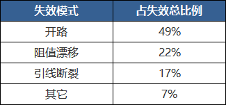
02
Table of proportion of failure modes to total failures
Wirewound resistor:
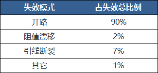
Non-wirewound resistor:
03
Failure mode mechanism analysis
The failure mechanism of resistors is multifaceted. Various physical and chemical processes that occur under working conditions or environmental conditions are the causes of resistor aging.
Structural changes of conductive materials:
The conductive film layer of a thin film resistor is generally obtained by vapor deposition, and has an amorphous structure to a certain extent. From a thermodynamic point of view, amorphous structures tend to crystallize. Under working conditions or environmental conditions, the amorphous structure in the conductive film layer tends to crystallize at a certain speed, that is, the internal structure of the conductive material tends to become densified, which often causes a decrease in resistance value. The rate of crystallization increases with increasing temperature.
Resistance wires or resistive films will be subjected to mechanical stress during the preparation process, causing distortion of their internal structures. The smaller the wire diameter or the thinner the film layer, the more significant the impact of stress will be. Generally, heat treatment can be used to eliminate internal stress. The residual internal stress may be gradually eliminated during long-term use, and the resistance value of the resistor may change as a result.
Both the crystallization process and the internal stress relief process slow down over time, but cannot be terminated during the use of the resistor. It can be considered that these two processes proceed at an approximately constant speed during the operating life of the resistor. The resistance changes related to them account for about a few thousandths of the original resistance value.
High-temperature aging of electrical load: In any case, electrical load will accelerate the aging process of the resistor, and the effect of electrical load on accelerating the aging of the resistor is more significant than the accelerated aging effect of increasing temperature. The reason is that the resistor body The temperature rise of the part in contact with the lead cap exceeds the average temperature rise of the resistor body. Generally, for every 10°C increase in temperature, the lifespan is shortened by half. If overload causes the temperature of the resistor to rise by 50°C above the rated load, the resistor's life will be only 1/32 of its normal life. The working stability of the resistor over a 10-year period can be assessed through an accelerated life test of less than four months.
DC load-electrolysis: Under the action of DC load, electrolysis causes the resistor to age. Electrolysis occurs in the grooves of the grooved resistor. The alkali metal ions contained in the resistor matrix are displaced in the electric field between the grooves, generating an ionic current. When moisture is present, the electrolysis process is more intense. If the resistance film is a carbon film or a metal film, it is mainly electrolytic oxidation; if the resistance film is a metal oxide film, it is mainly electrolytic reduction. For high-resistance thin film resistors, the consequences of electrolysis can increase the resistance, and film damage may occur along one side of the groove spiral. Conducting a DC load test in a hot and humid environment can comprehensively evaluate the anti-oxidation or anti-reduction properties of the resistor base material and film layer, as well as the moisture-proof performance of the protective layer.
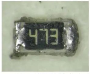
Typical appearance of the sample
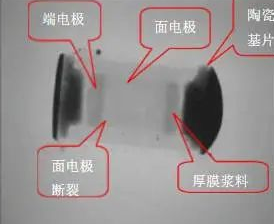
There is a broken hole in the surface electrode
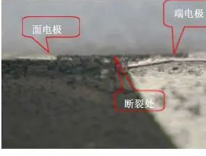
Surface electrolytic silver layer discontinuous band-shaped gaps
Vulcanization:
There are a batch of on-site After the instrument was used in a chemical plant for one year, the instruments began to malfunction one after another. After analysis, it was found that the resistance of the thick film chip resistor used in the instrument increased, and even became an open circuit. When the failed resistor was observed under a microscope, it was found that black crystalline material appeared on the edge of the resistor electrode. Further analysis of the composition revealed that the black material was silver sulfide crystals. It turns out that the resistor was corroded by sulfur from the air.
Gas adsorption and desorption:
The resistance film of the film resistor may always absorb a very small amount of gas on the grain boundaries, or on the conductive particles and binder parts, which constitute The intermediate layer between the crystal grains blocks the contact between the conductive particles, thereby significantly affecting the resistance value.
Synthetic film resistors are made under normal pressure. When working in vacuum or low pressure, part of the attached gas will be desorbed, which improves the contact between conductive particles and reduces the resistance value. Similarly, when a thermally decomposed carbon film resistor made in a vacuum is directly operated under normal environmental conditions, part of the gas will be adsorbed due to the increase in air pressure, causing the resistance to increase. If the unengraved semi-finished product is preset at normal pressure for an appropriate time, the resistance stability of the finished resistor will be improved.
Temperature and air pressure are the main environmental factors that affect gas adsorption and desorption. For physical adsorption, lowering the temperature can increase the equilibrium adsorption capacity, and increasing the temperature can do the opposite. Because gas adsorption and desorption occur on the surface of the resistor. Therefore, the impact on film resistors is more significant. The resistance change can reach 1%~2%.
Oxidation:
Oxidation is a long-term factor (different from adsorption). The oxidation process starts from the surface of the resistor and gradually penetrates deep into the interior. In addition to precious metal and alloy thin film resistors, resistors made of other materials will be affected by oxygen in the air. The result of oxidation is an increase in resistance. The thinner the resistive film layer, the more obvious the oxidation effect will be.
The fundamental measure to prevent oxidation is sealing (inorganic materials such as metal, ceramics, glass). Coating or potting with organic materials (plastics, resins, etc.) cannot completely prevent the protective layer from being permeable to moisture or air. Although it can delay oxidation or absorb gas, it will also bring about some new problems related to the organic protective layer. aging factors.
Influence of the organic protective layer:
During the formation of the organic protective layer, volatiles or solvent vapors from the condensation polymerization are released. The heat treatment process causes some volatile compounds to diffuse into the resistor body, causing the resistance value to rise. Although this process can last for 1 to 2 years, the time it takes to significantly affect the resistance value is about 2 to 8 months. In order to ensure the stability of the resistance value of the finished product, it is more appropriate to leave the product in the warehouse for a period of time before leaving the factory.
Mechanical damage:
The reliability of a resistor depends largely on the mechanical properties of the resistor. The resistor body, lead caps and lead wires should all have sufficient mechanical strength. Defects in the base body, damaged lead caps or broken leads can cause resistor failure.
2
Electrolytic capacitor failure
01
Depletion failure
The first explanation
Usually the end of the life of an electrolytic capacitor is judged when the capacitance drops below 80% of the rated (initial value). Due to the electrolyte filling of early aluminum electrolytic capacitors, the capacitance of aluminum electrolytic capacitors slowly decreases in the early stages of operation. As the working electrolyte continues to repair the anodized film damaged by impurities during the load process, the amount of electrolyte gradually decreases. In the later stages of use, due to the decrease in volatilization of the electrolyte, the increased viscosity of the electrolyte becomes difficult to fully contact the oxide film layer on the surface of the corroded rough aluminum foil, thus reducing the effective area of the plate of the aluminum electrolytic capacitor. , that is, the capacity of the anode and cathode aluminum foils decreases, causing a sharp drop in capacitance. Therefore, it can be considered that the capacity reduction of aluminum electrolytic capacitors is caused by the volatilization of the electrolyte. The main reason for the volatilization of electrolyte is high temperature environment or heat.
The second explanation
The reason why aluminum electrolytic capacitors heat up due to application conditions is that the aluminum electrolytic capacitors are working in rectification and filtering (including high-frequency rectification and filtering of switching power supply output), power When the power supply of the electric furnace is bypassed, the ripple (or pulsation) current flows through the aluminum electrolytic capacitor, causing loss in the ESR of the aluminum electrolytic capacitor and converting it into heat, causing it to generate heat.
When the aluminum electrolytic capacitor electrolyte evaporates more and the solution becomes thicker, the resistivity increases due to the increase in viscosity, which increases the equivalent series resistance of the working electrolyte, causing the capacitor loss to increase significantly. The loss angle increases. For example, for an electrolytic capacitor with an operating temperature of 105 degrees, when the maximum core package temperature is higher than 125 degrees, the viscosity of the electrolyte increases sharply, and the ESR of the electrolyte increases nearly ten times. .The increased equivalent series resistance will generate greater heat and cause greater volatilization of the electrolyte. Repeatedly in this cycle, the capacity of the aluminum electrolytic capacitor drops sharply, and may even cause an explosion.
The third explanation
Increased leakage current often leads to aluminum electrolytic capacitor failure. Excessive application voltage and excessive temperature will cause an increase in leakage current.
02
Pressure relief device action
In order to prevent the electrolyte in the aluminum electrolytic capacitor from being caused by the gas generated by the high-temperature boiling gas inside or the electrochemical process. The high internal pressure caused the aluminum electrolytic capacitor to explode. In order to eliminate the explosion of aluminum electrolytic capacitors, aluminum electrolytic capacitors with a diameter of 8 mm or more are equipped with pressure release devices. These pressure release devices operate and release the gas before the air pressure inside the aluminum electrolytic capacitor reaches a dangerous pressure that will cause the aluminum electrolytic capacitor to explode. . As the pressure relief device of the aluminum electrolytic capacitor operates, the aluminum electrolytic capacitor declares failure.
Aluminum electrolytic capacitor pressure relief device (cross in the middle)
The electrochemical process causes the pressure relief device to operate
The leakage current of the aluminum electrolytic capacitor is the electrochemical process , has been discussed in detail before and will not be repeated again. The electrochemical process will produce gases, and the accumulation of these gases will cause the internal pressure of the aluminum electrolytic capacitor to rise, eventually causing the pressure release device to operate to relieve pressure.
Excessive temperature causes the pressure release device to operate
If the temperature of the aluminum electrolytic capacitor is too high, it may be because the ambient temperature is too high. For example, there is a heating element near the aluminum electrolytic capacitor or the entire electronic device is out of place. High temperature environment;
The second reason why the aluminum electrolytic capacitor temperature is too high is that the core package temperature is too high. The fundamental reason why the core package temperature of aluminum electrolytic capacitors is too high is that excessive ripple current flows through the aluminum electrolytic capacitors. Excessive ripple current will cause excessive losses in the ESR of the aluminum electrolytic capacitor, resulting in excessive heat, causing the electrolyte to boil and produce a large amount of gas, causing the internal pressure of the aluminum electrolytic capacitor to rise sharply and the pressure relief device to operate.
03
Instantaneous over-temperature
Generally, every time the core temperature of the core package of an aluminum electrolytic capacitor decreases by 10°C, its lifespan will double. This core is located roughly at the center of the capacitor and is the hottest point inside the capacitor. However, when the capacitor heats up close to its maximum allowable temperature, for most types of capacitors at 125°C, the electrolyte is driven by the capacitor core package, causing the capacitor's ESR to increase to 10 times its original value. Under this effect, instantaneous over-temperature or over-current can permanently increase the ESR, causing capacitor failure. In applications with high temperatures and large ripple currents, special attention should be paid to the possibility of instantaneous over-temperature, and additional attention should be paid to the cooling of aluminum electrolytic capacitors.
04
Generation of instantaneous overvoltage
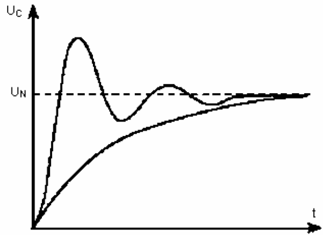
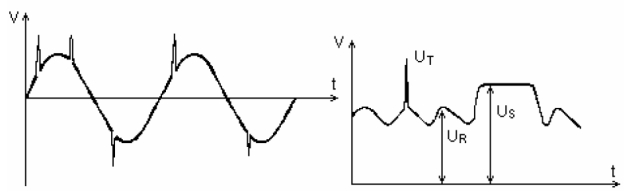
Power-on shock
During the power-on process, due to the filter inductor releasing stored energy to the filter capacitor, causing excessive instantaneous overvoltage of the filter capacitor.
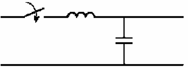
Power-on overvoltage diagram
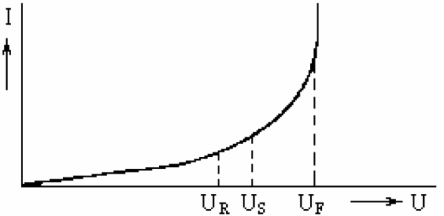
Prevention of capacitor overvoltage failure
Capacitors are easily broken down under overvoltage conditions, and instantaneous high voltages often occur in practical applications.
Choose an aluminum electrolytic capacitor with good transient overvoltage performance. Some RIFA aluminum electrolytic capacitors provide instantaneous overvoltage value parameters.
05
Drying up of electrolyte is the main reason for the failure of aluminum electrolytic capacitors
Reasons for drying up of electrolyte: natural volatilization of electrolyte and consumption of electrolyte.
The electrolyte evaporates naturally
The volatilization speed of the electrolyte increases with the temperature
The evaporation speed of the electrolyte is related to the sealing quality of the capacitor, no matter at high temperature It must still have good sealing performance under low temperature conditions.
Consumption of electrolyte
The electrochemical effect caused by leakage current consumes electrolyte, and the life of aluminum electrolytic capacitors decreases as the leakage current increases.
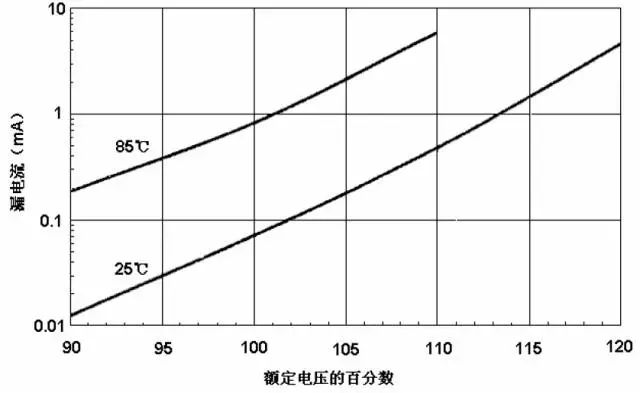
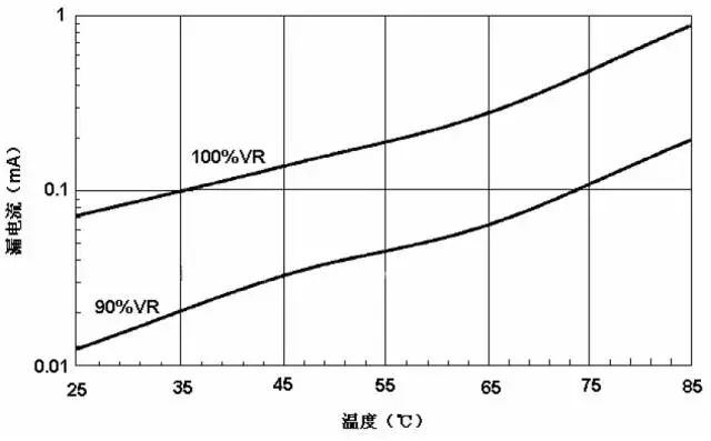
The leakage current increases with the increase of temperature: the leakage current at 25℃ is only less than one-tenth of the leakage current at 85℃. The leakage current increases with the increase of the applied voltage: the withstand voltage is 400V The leakage current of aluminum electrolytic capacitors at rated voltage is approximately 5 times the leakage current at 90% of rated voltage.
06
Drying up of electrolyte affects the life of aluminum electrolytic capacitors
Factors that affect the life of aluminum electrolytic capacitors: temperature
According to aluminum electrolytic Depending on the electrolyte of the capacitor, the maximum operating temperature of the aluminum electrolytic capacitor can be divided into:
General use, 85°C
General high-temperature use, 105°C
Special high-temperature use, 125℃
Car engine compartment, 140~150℃
For every 10℃ increase in temperature, the service life hours will be halved.
Factors affecting the life of aluminum electrolytic capacitors: rated life hours
According to the number of life hours, aluminum electrolytic capacitors can be divided into:
General purpose (normal temperature, Within 3 years), 1000 hours
General use (normal temperature, hopefully a longer time), more than 2000 hours
Industrial grade, longer life hours
Factors affecting the life of aluminum electrolytic capacitors: electrolyte
The amount of electrolyte determines the life of aluminum electrolytic capacitors.
Factors affecting the life of aluminum electrolytic capacitors: application conditions
High temperature shortens the life of aluminum electrolytic capacitors; high ripple current shortens the life of aluminum electrolytic capacitors; too high working voltage shortens the life of aluminum electrolytic capacitors life.
07
Parameters and application conditions that affect the life of aluminum electrolytic capacitors
The relationship between operating voltage and leakage current
The relationship between operating voltage and leakage current
The relationship between the leakage current and the applied voltage of the 450V/4700μF/85℃ aluminum electrolytic capacitor produced by a certain company is as follows:
The relationship between temperature and leakage current
Produced by a company The relationship between the leakage current of the 450V/4700μF/85℃ aluminum electrolytic capacitor and the ambient temperature is as follows:
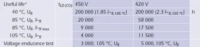
The influence of temperature, voltage and ripple current on lifespan
Taking a certain electronic ballast Take aluminum electrolytic capacitors as an example.
The service life of aluminum electrolytic capacitors under different voltage and temperature conditions is different. The table is as follows:
The derating life characteristics of an aluminum electrolytic capacitor used in an electronic ballast are as shown below:
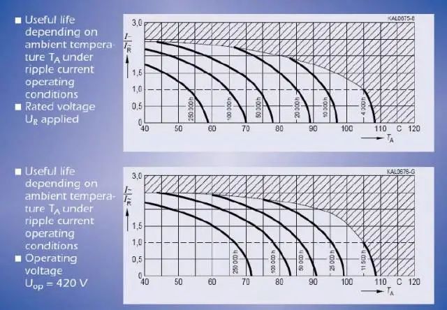
Someone The overvoltage life characteristics of aluminum electrolytic capacitors used in electronic ballasts are as shown below:
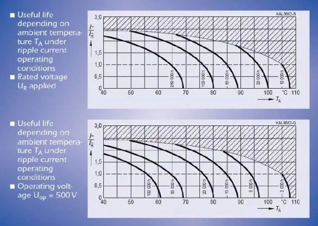
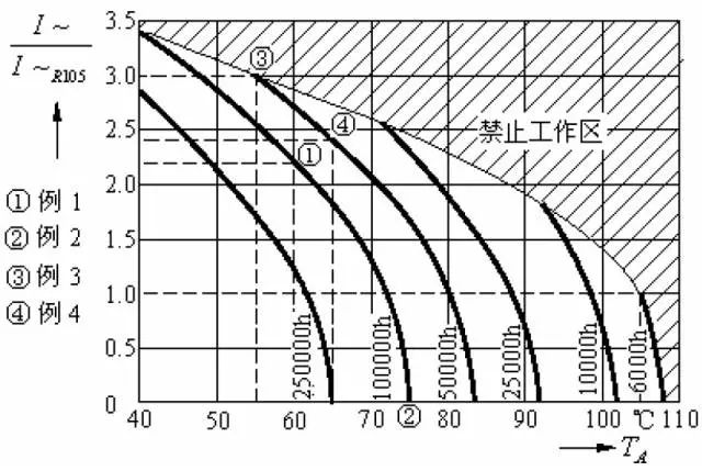
The relationship between the life of aluminum electrolytic capacitors, temperature and ripple current is as shown below:
3
Inductor Failure analysis
Inductor failure modes: out-of-tolerance, open circuit, and short circuit in inductance and other properties.
Failure mechanism of molded wire-wound chip inductors:
The mechanical stress generated in the magnetic core during processing is relatively large and has not been released;
Inside the magnetic core There are impurities or holes in the magnetic core material itself that are uneven, which affects the magnetic field condition of the magnetic core and causes deviations in the magnetic permeability of the magnetic core;
Due to sintering cracks produced after sintering;
When the copper wire is connected to the copper strip by dip soldering, the coil part is splashed with tin liquid, which melts the insulating layer of the enameled wire, causing a short circuit;
The copper wire is thin, causing false soldering when connected to the copper strip. Open circuit failure.
01
Solder resistance
The sensitivity of low-frequency chip increases by 20% after reflow soldering.
Because the reflow temperature exceeds the Curie temperature of the low-frequency chip material, demagnetization occurs. After the sensor is demagnetized, the magnetic permeability of the sensor material returns to its maximum value, and the sensor value increases. The generally required control range is that after the chip is resistant to welding heat, the increase in sensitivity should be less than 20%.
A possible problem caused by soldering resistance is that sometimes when small batches of manual soldering are performed, the circuit performance is all qualified (at this time, the entire chip is not heated, and the increase in sensitivity is small). However, when placing large quantities of chips, it was found that the performance of some circuits was degraded. This may be because after reflow soldering, the chip inductance will increase, which affects the performance of the circuit. In places where the accuracy of the chip sensor is strictly required (such as signal receiving and transmitting circuits), more attention should be paid to the soldering resistance of the chip sensor.
Testing method: First measure the sensor value at normal temperature, then immerse the sensor into the molten solder pot for about 10 seconds and take it out. After the tablet has completely cooled down, measure the new value of the tablet. The percentage increase of the sensor is the solderability of the sensor
02
Solderability
Introduction to electroplating
When the reflow soldering temperature is reached, metallic silver (Ag) will react with metallic tin (Sn) to form a eutectic, so tin plating cannot be done directly on the chip-like silver terminals. Instead, the silver terminal is first plated with nickel (about 2um) to form an isolation layer, and then plated with tin (4-8um).
Solderability Test
Clean the end of the chip to be tested with alcohol, immerse the chip in the molten solder can for about 4 seconds, and then take it out. If the solder coverage rate of the chip sensor terminal reaches more than 90%, the solderability is qualified.
Poor solderability
1) Terminal oxidation: When the chip is affected by high temperature, moisture, chemicals, oxidizing gases (SO2, NO2, etc.), or has been stored for too long long, causing the metal Sn on the sensor tip to be oxidized into SnO2, and the sensor tip to darken. Since SnO2 does not form a eutectic with Sn, Ag, Cu, etc., the chip solderability is reduced. Shelf life of tablet products: half a year. If the sensor terminal is contaminated, such as oily substances, solvents, etc., it will also cause a decrease in solderability.
2) The nickel plating layer is too thin and eats silver: If nickel is plated, the nickel layer is too thin and cannot play an isolation role. During reflow soldering, the Sn on the sensor terminal reacts with its own Ag first, which affects the fusion of Sn on the sensor terminal and the solder paste on the pad, causing silver eating and reducing the solderability of the sensor. .
Judgment method: Dip the chip into the molten solder can for a few seconds and take it out. If you find that there are potholes at the end or even the porcelain body is exposed, you can judge that there is a phenomenon of silver eating.
03
Poor welding
Internal stress
If the chip has a large internal stress during the production process and is not Take measures to eliminate stress. During the reflow soldering process, the attached chip will stand up due to the influence of internal stress, commonly known as the tombstone effect.
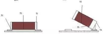
To determine whether the chip has large internal stress, a simpler method can be adopted: take several hundred pieces of chip, put them into a general oven or low-temperature furnace, raise the temperature to about 230°C, keep them warm, and observe Conditions inside the furnace. If you hear a crackling sound or even the sound of the film jumping up, it means that the product has large internal stress.
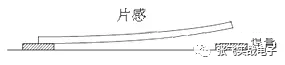
Component deformation
If the chip-like product has bending deformation, there will be an amplification effect during welding.
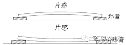
Poor welding, virtual welding:
Welding is normal:
Improper pad design:
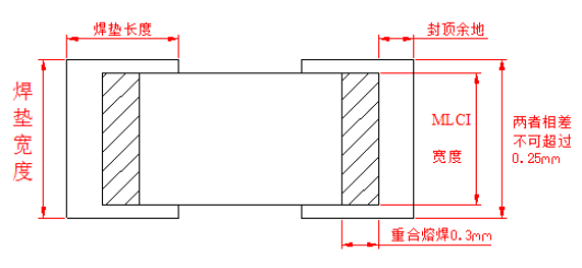
Various elements of MLCI after welding:
a. Both ends of the pad should be designed symmetrically to avoid uneven sizes, otherwise the melting time and wetting force at both ends will be different
b. The length of the welding should be more than 0.3mm (that is, the metal end of the chip) The overlapping length of the header and the pad)
c. The length of the pad margin should be as small as possible, generally no more than 0.5mm.
d. The width of the pad itself should not be too wide. Compared with the MLCI width, its reasonable width should not exceed 0.25mm
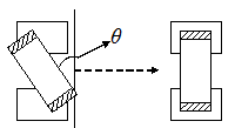
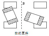
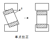
Poor patching
When patching During chipping, due to the unevenness of the solder pad or the sliding of the solder paste, the chip feel is shifted by the θ angle. Due to the wetting force generated when the solder pad melts, the above three situations may occur. Among them, self-alignment is the main one, but sometimes it may be pulled more obliquely or straightened at a single point, and the chip is pulled to a pad. on, or even pulled up, standing obliquely or upright (the phenomenon of erecting a monument). Currently, placement machines with theta angle offset visual inspection can reduce the occurrence of such failures.
Soldering temperature
The soldering temperature curve of the reflow soldering machine must be set according to the requirements of the solder. Try to ensure that the solder at both ends of the chip is melted at the same time to avoid the different times at which the wetting force is generated at both ends, resulting in chipping. Shift occurs during welding. If poor soldering occurs, you can first confirm whether the temperature of the reflow soldering machine is abnormal or the solder has changed.
Inductors are easily damaged under rapid cooling, rapid heating or local heating. Therefore, special attention should be paid to the control of the welding temperature during welding, and the welding contact time should be shortened as much as possible.
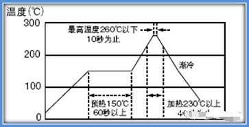
Reflow soldering recommended temperature profile
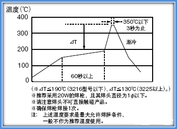
Recommended temperature curve for manual soldering
04
Open circuit on the machine
Welding, soldering contact Defective
Remove the chip from the circuit board and test to see if the performance of the chip is normal
Current burn-through
If the chip is selected, the rating of the magnetic beads A small current or a large inrush current in the circuit will cause the current to burn through, causing the chip or magnetic beads to fail, causing the circuit to open. Remove the sensor from the circuit board and test it. The sensor fails and sometimes shows signs of burnout. If current burn-through occurs, the number of failed products will be larger, and the failed products in the same batch will generally reach the hundredth grade or above.
Soldering open circuit
The rapid cooling and rapid heating during reflow soldering causes stress inside the chip, which leads to the enlargement of defects in the chip with a very small number of internal open circuit risks, causing the chip to become larger. Feeling opens the way. Remove the chip
