-
Mail us
contact@tiger-transformer.com -
Phone us
(+86)15655168738 -

Mail us
contact@tiger-transformer.comPhone us
(+86)15655168738
Suppression Measures for Differential Mode Conducted Emission of Switching Power Supply
The solution to the differential mode conducted emission of switching power supply from the source is to reduce the spectrum envelope of the switching current, thereby reducing noise. each frequency component of the source. The amplitude of the switching current is determined by the rated power of the power supply and cannot be changed; increasing the on/off time of the switching tube can reduce the turning frequency and effectively reduce the high-frequency component of the differential mode voltage. However, due to the conduction / There will be energy loss during the shutdown period, so it will increase the power loss and reduce the efficiency of the switching power supply. This needs to be weighed. Therefore, it is difficult to solve the implementation from the source.
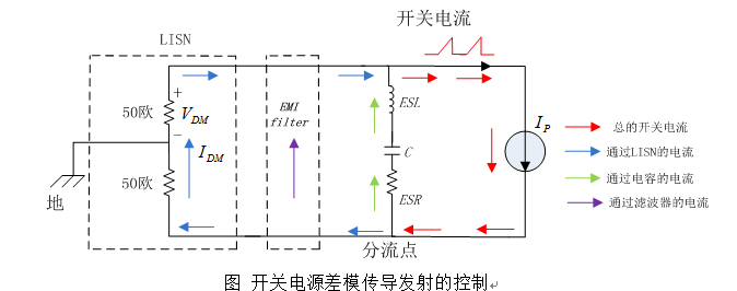
Next, let’s analyze the coupling path, based on the previous analysis , reducing the ESL and ESR of the filter capacitor can reduce the impedance of this branch, thereby allowing more switching current frequency components to flow from the filter capacitor and reducing the switching current flowing through the LISN. However, since the filtering and energy storage capacitor C is a large-capacity capacitor, the degree of reduction of its ESL and ESR is limited.
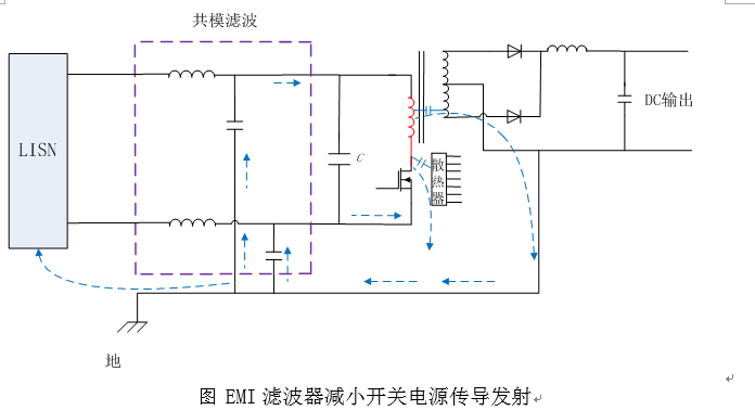
We mainly rely on EMI filters to solve differential mode conducted emissions. EMI filters can suppress the switching current from flowing to LISN, and at the same time provide a low impedance between lines, allowing more switching current to return from the filter to LISN. source, reducing the switching current flowing through the LISN, thereby reducing differential mode conducted emissions. The energy does not disappear into thin air, the filter just provides a return path.
The following figure is the circuit diagram of our most commonly used filter.
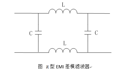
About EMI filter design is an important issue in electromagnetic compatibility Content, we will take out special chapters later to explain in detail from theory, design, device selection, layout, etc. Here we only introduce it to illustrate that EMI filters are the main method to solve the differential mode conduction emission of switching power supplies.
** Common-mode conducted emission suppression measures for switching power supplies**
Increasing the on/off time of the switching tube can also reduce the high-frequency component of common-mode noise from the source suppresses noise, but increases power loss.
The following measures can be taken for the coupling path:
(1) Add shielding between the switch tube and the radiator. But be sure to pay attention to the grounding point of the shielding layer, which must be connected to the source of the MOS tube, which is the reference point of the common-mode voltage source.
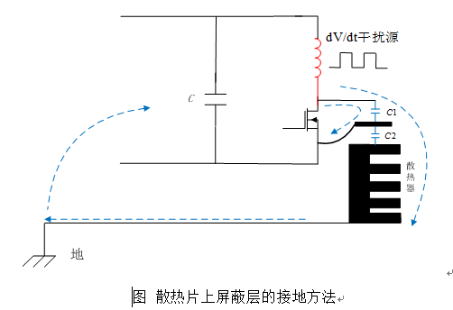
Because the reference point of the common mode voltage source MOS tube source, so the shielding layer should be connected to the source of the MOS tube, which provides a low-impedance shunt path for the common-mode current, so that more common-mode current returns to the source of the MOS tube through the shielding layer and its ground wire , this part of the common mode current will not cause conducted emission. The remaining common mode current flows from the radiator to the chassis and then flows back through the LISN. This part of the common mode current will contribute to the conducted emission.
There are shielded thermally conductive rubber sheets on the market. This thermally conductive rubber sheet has a layer of copper foil embedded in the middle. When used, the copper foil is directly connected to the source of the MOS tube, which can effectively reduce the Common mode current conduction emissions.
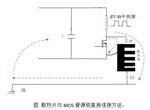
For power supplies with lower power, the heat sink does not match Chassis connection. At this time, the heat sink can be connected to the source of the MOS tube, which can also reduce conducted emissions.
(2) Add shielding between the primary side and secondary side of the transformer. Also pay attention to the grounding point of the shielding layer, which must be connected to the source of the MOS tube, which is the reference point of the common-mode voltage source.
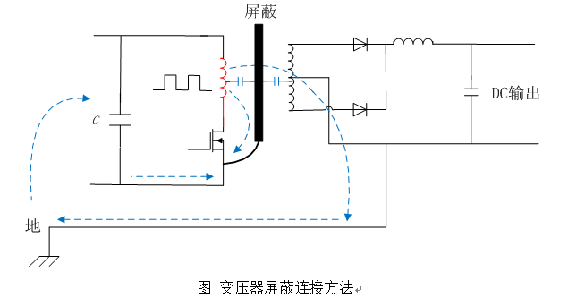
Spurs between the primary and secondary sides of the transformer Capacitance is the main cause of common-mode current at the output. As can be seen from the figure above, by shielding the transformer and connecting the shielding layer to the source of the MOS tube, this is equivalent to adding a low-impedance path for the common-mode current, allowing more common-mode current to pass through the shielding layer and its The ground wire returns to the source of the MOS tube. This part of the common mode current no longer passes through the LISN and no longer contributes to the conducted emission; the remaining common mode current passes from the secondary side of the transformer through the chassis and finally returns through the LISN.
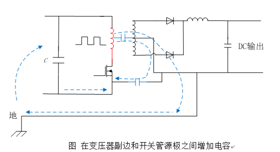
(3) Add a capacitor between the secondary voltage reference point of the transformer and the source of the MOS tube. Adding a capacitor allows the common-mode current that originally flows through the output power line to bypass directly back to the common-mode voltage source, thereby reducing the common-mode current flowing to the output loop.
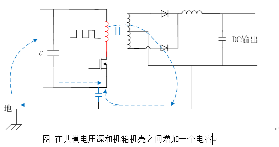
(4) Between the common mode voltage source and the chassis Add a capacitor between the shells. Provides a low-impedance path for common-mode current coupling back to the output, thereby reducing common-mode current return from the input power line, and also facilitates common-mode current return coupling from the heat sink to ground. But pay attention to the size of the leakage current.
(5) EMI filter. Adding an EMI filter to the power input of a switching power supply can effectively reduce the measured common-mode conducted emissions of the switching power supply. Because the EMI filter has a common-mode filter capacitor to the chassis ground, it provides a low-impedance common-mode return path, thereby reducing the common-mode current flowing back from the LISN; on the other hand, because the power line is serially connected with a common-mode inductor , increases the common-mode impedance of the power line, further reducing the common-mode current flowing back from the LISN and power line. The common mode inductor and common mode capacitor are used together to reduce the common mode conducted emission measurement value of the switching power supply.